Home > Active Components > American Megatrends
American Megatrends Incorporated (AMI)
 American Megatrends Incorporated (AMI), an American hardware and software company, specializes in PC hardware and firmware. The company started as a manufacturer of complete motherboards.As hardware activity moved progressively to overseas, AMI continued to develop BIOS firmware for major motherboard manufacturers.
American Megatrends provides BIOS/UEFI firmware for server, embedded, tablet, client, and ARM products; BIOS/UEFI tools and utilities, such as debug and diagnostic tools, pre-boot utilities, and development systems; MegaRAC remote management firmware/software solutions for in/out-of-band management; MegaRAC Composer, a pod management software solution that allows users to browse physical resources at the rack, chassis, and system level through a Web-based user interface; Android products and solutions for Intel hardware platforms; and enclosure management controller ASICs that provides LED and sensor control for SAS/SATA drives.
American Megatrends also provides engineering services, including custom design services for hardware, software, and firmware solutions; mobile application development and support services for clients in the mobile technology; and platform validation and testing services for guaranteed fault-proof testing of clients’ hardware, software, and firmware products.
The BIOS serves as a bridge between the hardware components of a computer and the operating system, allowing the system to initialize, configure hardware settings, and provide a platform for the operating system to run on. AMI BIOS provides a comprehensive set of functions and features that enable efficient system startup, hardware detection, and configuration.
AMI BIOS is known for its user-friendly interface, ease of use, and extensive compatibility with a wide range of computer systems and components. It offers a graphical user interface (GUI) that allows users to navigate and modify various BIOS settings using a mouse and keyboard.
One notable feature of AMI BIOS is its support for Plug and Play (PnP) technology, which simplifies the process of adding new hardware devices to the computer. Additionally, AMI BIOS incorporates advanced power management features that help optimize energy usage and improve system efficiency.
AMI regularly releases BIOS updates and enhancements to improve system performance, add new features, and address security vulnerabilities. These updates can typically be obtained from the motherboard manufacturer’s website or AMI’s official website.
Overall, AMI BIOS plays a crucial role in the functioning of a computer system, providing essential firmware capabilities for hardware initialization and system configuration. Its reliability, compatibility, and user-friendly interface have made it a popular choice among computer manufacturers and users alike.
BIOS Chip Installation and Removal Guide
Adjusting Pins Before Installation
- Pin Adjustment: If the chip’s pins are too spread out, place the chip sideways on a solid surface. Carefully press the body of the chip against the four lower pins to adjust them. If pins are bent, use tweezers with flat ends to straighten them by gripping the bent pin and applying light pressure.
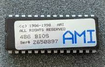
Removing a Chip from a DIL/DIP Socket
- Using Two Screwdrivers: Insert two small screwdrivers on opposite sides of the chip between the socket and the chip. Apply gentle pressure on both sides to lift the chip out.
- Using One Screwdriver: Gently lift one side of the chip by 1-2 mm, then switch to the other side to avoid bending the pins.
Installing a Chip in a DIL/DIP Socket
- Align the Markings: DIL chips usually have a marking (e.g., a notch) on one side, and DIL sockets often have a corresponding notch or printed number. Align the chip’s marking with the socket’s marking, or match the chip’s “1” with the socket’s “1.”
- Insert Carefully: Ensure all pins are correctly positioned before pressing the chip into the socket.
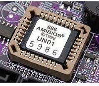
Removing a Chip from a PLCC Socket
- Using Two Screwdrivers: Insert the screwdrivers into the diagonal slits on opposite sides of the socket. Gently lift one side by 1 mm, then switch to the other side.
- Using a PLCC Extractor: Insert the extractor hooks into the socket slits, then squeeze the extractor legs together until the chip pops out. Do not pull on the extractor.
- Alternative Method: A bent paper clip can also be used to lift the chip by inserting it into the socket slit.
Installing a Chip in a PLCC Socket
- Align the Markers: PLCC chips have a flat corner as a marker. Align the chip’s marker with the corresponding marker on the socket or the number “1” on the circuit board.
- Insert Carefully: Press the chip into the socket, ensuring all pins are aligned.
After Installation
- Boot the PC, enter the BIOS setup, and load the “Default/Optimized Settings.”
- AMD

- Allwinner

- Altera


- STMicroelectronics

- Qualcomm

- Atmel