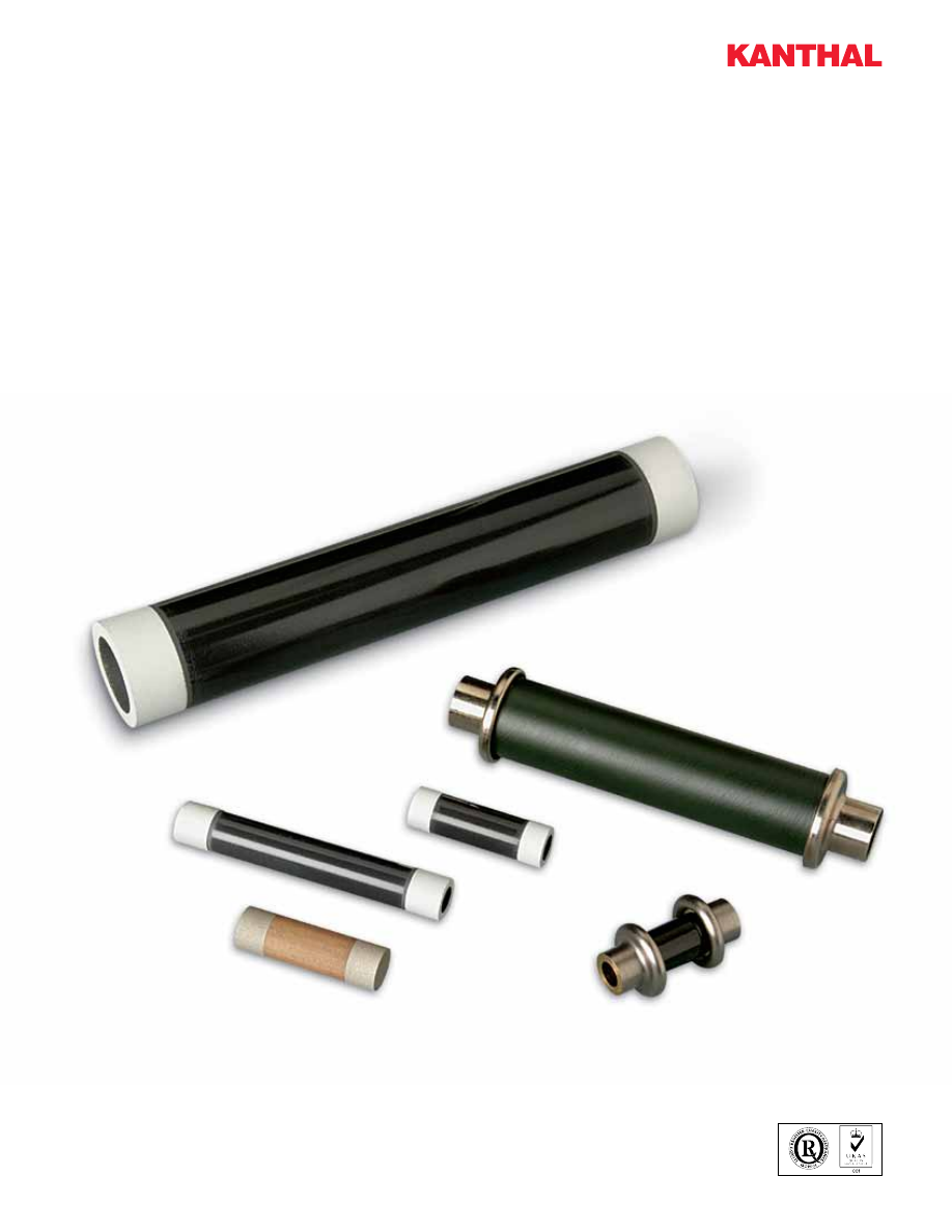
background image

Series 800 and 1000 

Tubular Resistors 


Product Information

1 AA Series 800 1000 Tubular Resistors-html.html
background image

Contact Information

Series 800 and 1000 Tubular Non-Inductive Bulk Ceramic 

Resistors provide excellent performance for high peak power 

or high-energy pulses. Bulk construction advantageously 

produces an inherently non-inductive resistor; and it allows 

energy and power to be uniformly distributed through the 

entire ceramic resistor body – there is no film or wire to fail. 

We offer a full line of rugged, reliable ceramic resistors.
We offer three distinctly different ceramic materials to afford 

the designer with unique components to meet the most 

demanding requirements:

Tubular Resistors – Series 800 and 1000


Type SP


resistors are composed of 

materials that withstand high operating 
temperatures resulting in high power 
dissipation. Maximum continuous 
operating temperature is specified at 
350°C. This type is suitable for use in 
oil without an oil-resistant coating

.

Type AS


resistors are best suited 

for high energy and voltage pulse 
applications. Maximum continuous 
operating temperature is specified at 
230°C. The standard dielectric coating 
is recommended for use in air, and the 
oil-resistant coating is recommended 
for use in oil.

Type A


is a high-power non-inductive 

resistor used when high resistance is 
required.

• Motor drive circuits

• Snubber circuits

• High-frequency circuits

• RF dummy loads

• Dynamic braking

• Transformer protection

• Harmonic filter

• Impulse generators

• High-voltage circuits

• X-ray equipment

• High voltage power supplies

• Laser/Imaging equipment

• Capacitor charge/discharge

• Bleeder

• Capacitor charge/discharge

… just to name a few uses.

Globar bulk ceramic resistors are problem solvers for:

Ordering Information

Part Numbering System

Example Part Number:  890AS101KDS    890AS  101  K  DS

Construction Type Resistance Value (Ω)

For ≥ 10 Ω:  First 2 digits 

are significant figures, third 

digit is number of zeros to 

follow, 

e.g. 101 = 100 Ω
For < 10 Ω:  An R replaces 

the decimal point,  

e.g. R50 = 0.50 Ω,  

7R5 = 7.5 Ω

Resistance Tolerance

J = + 5%

K = + 10%

L = + 20%

Terminal End Options

Type SP

Type AS

Type A

SP

No Suffix = Standard aluminum metalized ends
No-arc terminal not available on SP products

G = Radial tab, riveted and soldered
G1 = Radial tab, riveted and no solder

AS

DS  = Standard dielectric coating and silver 

metalized ends  
N = No-arc terminal and dielectric coating
NO = No-arc terminal with oil resistant coating

DG = Radial tab, riveted and soldered with 

dielectric coating
DG1 = Radial tab, riveted and no solder with 

dielectric coating
GO = Radial tab, riveted and soldered with oil 

resistant coating

TO = Soldered end and oil resistant coating

A

No Suffix  = Standard nickel metalized ends
D = Dielectric coating
DG = Radial tab, riveted and soldered with 

dielectric coating

N = No-arc terminal and dielectric coating
NO = No-arc terminal with oil resistant coating

DG = Radial tab, riveted and soldered with 

dielectric coating
DG1 = Radial tab, riveted and no solder with 

dielectric coating
GO = Radial tab with oil resistant coating

TO = Soldered end and oil resistant coating

Sandvik Heating Technology USA, 495 Commerce Drive, Ste. 7 

Amherst, NY 14228-2311, USA 


Phone: (716) 691-4010   Fax: (716) 691-7850

Toll-Free: 877-GLOBAR-2  (877-456-2271) 

E-mail: sales.globar@kanthal.com

Website: www.globar.com

1 AA Series 800 1000 Tubular Resistors-html.html
background image

High Voltage Resistors – High Power Resistors – High Energy Resistors

Series 800 and 1000 Tubular Resistors are available in a wide variety of sizes and terminations from 2˝ to 24˝ in length and ½˝ to 
2˝ in diameter. These resistors can handle up to 1000 watts, 165 kJ and 165 kV in resistance values from 1 ohm to 1 megohm.

A 1/16

B 1/32

C Nom.

D 1/18

Metallized Ends

Type

A

B

C  

(SP & AS)

C  

(A)

D

884 SP

2.0

0.50

0.22

0.25

885 SP,  AS, & A

2.5

0.75

0.50

0

0.50

886 SP,  AS, & A

5.0

0.75

0.50

0

0.62

887 SP,  AS, & A

6.0

1.00

0.75

0.5

0.50

888 SP,  AS, & A

8.0

1.00

0.75

0.5

0.88

889 SP,  AS, & A

12.0

1.00

0.75

0.5

0.88

890 SP,  AS & A

18.0

1.00

0.75

0.5

0.88

891 SP

18.0

2.00

1.50

– 

1.00

892 SP

24.0

2.00

1.50

– 

1.00

1026 AS

6.0

1.50

1.00

– 

0.50

1028 AS

8.0

1.50

1.00

– 

0.88

1032 AS

12.0

1.50

1.00

– 

0.88

1038 AS

18.0

1.50

1.00

– 

0.88

1044 AS

24.0

1.50

1.00

– 

0.88

Special sizes are available. Consult factory.

Dimensions – Inches

Electrical Specifications

Length and 

Diameter

Type

Resistance Available

(ohms) Min. to Max.

Average 

Power @ 40°C 

(watts)

Peak* Energy 

(joules)

Peak* 

Voltage** 

(volts)

2˝ x 1/2˝

884SP

1.0

200

22.5

250

1,000

2 1/2˝ x 3/4˝

885SP

1.0

130

45

250

1,000

885AS

6.0

1200

15

2,800

8,000

885A

1500

220K

15

750

3,750

5˝ x 3/4˝

886SP

1.0

330

90

500

4,000

886AS

15.0

3300

30

7,000

20,000

886A

3900

390K

30

1,500

10,000

6˝ x 1˝

887SP

1.0

330

150

1,600

4,000

887AS

12.0

3300

50

13,000

30,000

887A

3900

390K

50

6,000

12,000

6˝ x 1 1/2˝

1026AS

5.0

1200

70

30,000

30,000

8˝ x 1”

888SP

1.0

390

190

2,100

6,000

888AS

15.0

3900

75

16,500

45,000

888A

4700

470K

60

7,500

15,000

8˝ x 1 1/2˝

1028AS

6.5

1900

100

46,000

45,000

12˝ x 1˝

889SP

1.0

680

275

3,200

10,000

889AS

25.0

6800

100

27,000

75,000

889A

8200

680K

90

12,500

25,000

12˝ x 1 1/2˝

1032AS

9.0

2500

150

75,000

75,000

18˝ x 1˝

890SP

1.0

1000

375

4,200

16,000

890AS

40.0

10K

150

43,000

120,000

890A

12K

1M

125

20,000

40,000

18˝ x 1 1/2˝

1038AS

15.0

3800

225

119,000

120,000

18˝ x 2˝

891SP

1.0

450

750

15,000

16,000

24˝ x 2˝

892SP

1.0

600

1000

17,500

22,000

24˝ x 1 1/2˝

1044AS

20.0

4800

300

164,000

165,000

*  Allowable peak energy/voltage will depend on the resistance value. Consult factory.
** Derate by 50% with oil resistant coating on Type AS resistors. Energy ratings are based on pulses <10 milliseconds.  Type SP ratings can be 

substantially greater for longer pulses. Consult factory.

1 AA Series 800 1000 Tubular Resistors-html.html
background image

Termination Metals

Electrical connection to the resistive bodies of resistors is made by metal end bands. The standard metal is aluminum 
for Type SP, silver for Type AS and nickel for Type A. Special terminations of brass, copper or soldered ends are also 
available.

Mounting Clips

In most cases, connections to the resistors may 
be made by using these stock clips.

Dimensions – Inches

Part No.

Resistor 

OD

Holes

A

B

C

D

E

F

T

V

W


35370

1/2

1

0.620

0.090

0.560

0.500

N/A

0.093

0.020

0.188

0.375

35267

3/4

1

0.940

0.155

0.830

0.750

N/A

0.144

0.020

0.312

0.625

35268

1

2

1.230

0.170

1.070

1.000

0.320

0.128

0.024

0.156

0.625

35371

1 1/2

2

1.650

0.100

1.650

1.500

0.925

0.103

0.032

0.250

0.500

35269

2

2

2.375

0.544

1.080

2.000

0.375

0.188

0.043

0.375

0.750

Material: Beryllium Copper      Finish: Electro Tin Plate

Aluminum Connector Caps

Dimensions – Inches

Part

No.

Resistor  

Diameter

OD

OD-

1

W

E

ID

A

B

C

Threaded Holes

 36075

3/4

1 1/2

1 3/8

3/4

0.830

3/8

3/16

3/16

.50

M3 x .5P x 3/16˝ DP

 36100

1

1 3/4

1 5/8

1

1.080

1/2

3/16

3/8

.75

M3 x .5P x 3/16˝ DP

 36150

1 1/2

2 1/4

2 1/8

1

1.580

3/4

3/16

3/8

.75

M4 x .7P x 3/16˝ DP

 36200

2

3

2 3/4

1 1/8

2.080

1

5/16

7/16

.88

M5 x .8P x 1/4˝ DP

Across Flats

OD-1

ID

E

OD

B

W

C

A

A

(2) Threaded Holes- Each Side 

Contacts - Beryllium Copper

Maximum 

Insertion Length

C max.

.001"

D 0.015"

A max.

B

W

F 0.003"

0.005"

0.005"

E


1 AA Series 800 1000 Tubular Resistors-html.html
background image

Optional No-Arc Termination 

“N” Suffix

Optional Radial Tab Termination

“G1” suffix - riveted only

“G” suffix - riveted with solder

A

Same as Standard Resistor Length

Overall Length = L 1/16"

B Hole

Resistor Diameter

Diameter = D 1/32"

Same as Standard


 W

1


W

1

D1 1/32

W

D

Resistor Length 1/16

Overall Resistor Same as Standard

D2

Dimensions – Inches

D

1

D2

D

W

1

1.56

1

3/4

1 1/2

1.84

1

3/4

Dimensions – Inches

D

W

1

A

B

1/2

3/16

17/32

0.062

3/4

3/8

25/32

0.156

1

3/8

25/32

0.156

1 1/2

3/8

25/32

0.156

2

5/8

1.25

0.281

D1 1/32

W

D

Resistor Length 1/16

Overall Resistor Same as Standard

D2

A

Same as Standard Resistor Length

Overall Length = L 1/16"

B Hole

Resistor Diameter

Diameter = D 1/32"

Same as Standard


 W

1


W

1

1 AA Series 800 1000 Tubular Resistors-html.html
background image

Characteristics

Type SP

Type AS

Type A

Operating Temperature (1)

-55°C to +350°C

-55°C to +230°C

-55°C to +230°C

Resistance Temperature Coefficient

+0.2 to -0.08 %/°C

+0.0 to -0.08 %/°C

+0.0 to -0.2 %/°C

Voltage Coefficient 

  Max. % per kilovolt per inch active length

-1.0%

-1.0%

––

Short Time Overload

   Max. % change after 10 cycles of 1000% rated 

power 5 sec. On, 90 sec. Off

± 5%

± 2% 

––

Load Life


  Max. % change after 1,000 hours at rated power

± 5%

± 5%

––

Thermal Shock 

  Max. % change after 10 cycles -55°C to +125°C

± 3%

± 3%

––

Moisture Resistance 

   Max. % change when tested per MIL-STD-202, 

Method 103

± 5%

± 5%

± 5%

(1) Note: When required, Type SP material can withstand short periods of use at red-heat conditions, i.e. up to 550°C to 600°C

Typical Physical 

Properties

SP Resistors

AS Resistors

A Resistors

Density

2.2 - 2.4 gm/cc

2.2 - 2.6 gm/cc

2.2 - 2.6 gm/cc

Specific Heat

0.24 - 0.26 cal/gm -°C

0.23 - 0.25 cal/gm -°C

0.23 - 0.25 cal/gm -°C

Thermal Conductivity

0.14 - 0.16 cal/(cm - °C - sec) 0.003 - 0.006 cal/(cm - °C - sec)

0.003 - 0.006 cal/(cm - °C - sec)

Power Rating Curves 

(Curve is Typical for Resistor 

Midpoint with Horizontal 

Orientation in Still Air)

Power ratings are based on 

maximum allowable surface 

temperature in still air at 40˚C 

ambient temperature.

Resistor Surface  

Temperature  

Rise Versus Power

120

100

100

200

300

400

80

60

40

20

0

0

%

 of

 Rated

 Power

Ambient Temperature, ˚C

23 0 ˚C

35 0 ˚C

TYPE  SP 

TYPE  AS & A

% of Rated Power

0

340
300

200

100

Temperature Rise

C

0

20

40

60

80

100

120

120

100

100

200

300

400

80

60

40

20

0

0

%

 of

 Rated

 Power

Ambient Temperature,

˚C

23 0

˚C

35 0

˚C

TYPE  SP 

TYPE  AS & A

% of Rated Power

0

340
300

200

100

Temperature Rise

C

0

20

40

60

80

100

120

AS Resistor

SP Resistor

Disclaimer: 

The information contained in this document is for illustrative purposes only. The data and examples are only general recommendations, and not a warranty or a 

guarantee that such data will function in individual/specific cases. The purchaser of a Kanthal product has the responsibility to control the applicability of Kanthal’s products 
in a specific application before using them.

® KANTHAL is a registered trademark of Kanthal Group companies in Sweden and other countries.

Kanthal – a Member of the Sandvik Group

The Sandvik Group is a global high technology enterprise with 41,700 employees and annual sales of approximately SEK 72 billion. Sandvik spends about 4 percent of its turno-
ver on research and development. As a member of the Sandvik Group, Kanthal has full access to world-class competence within materials and process technology, as well as 
Sandvik’s R&D-center in Sweden, which is one of the most distinguished in the world. Through Sandvik’s global sales organization Kanthal is represented in 130 countries.

Sandvik Heating Technology USA, 495 Commerce Drive, Ste. 7, Amherst, NY 14228-2311, USA  Phone: (716) 691-4010  Fax: (716) 691-7850  

 E-mail: sales.globar@kanthal.com  Website: www.globar.com

@ 2013 All Rights Reserved Form #: Tubular 08/13