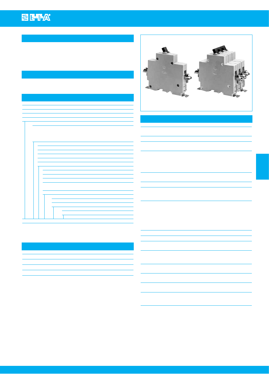
Isolation Switches 911/912/913-...
www.e-t-a.com
Issue B
4
- 65
4
Description
Typical applications
Technical data
Single, two and three pole isolators to EN 60947 / IEC 60947 with toggle
actuation. Designed for rail, panel or surface mounting. Options include
auxiliary contacts and remote electrical disconnection.
For circuit breaker versions see types 410, 520, 530.
Control systems, industrial equipment.
911-K
913-K
Voltage rating
AC 240 V; 3 AC 415 A; 3 AC 500 V;
DC 110 V
Current rating range
32 A, 63 A, 125 A
Auxiliary contact rating
6 A at AC 240 V or DC 28 V;
1 A at DC 110 V
Electrical remote disconnection (FA)
operating voltage
DC 12 V or DC 24 V
operating current
approx. 18 A or 12 A
max. pulse time
10 ms < t
ON
< 20 ms /t
OFF
> 10 s
switching time
< 20 msec
Typical life
10,000 operations at I
N
20,000 operations mechanical
Ambient temperature -40...+75 °C (-40...+167 °F)
Insulation co-ordination rated impulse
pollution
(IEC 60664 and 60664A)
withstand voltage
degree
6 kV
3
Dielectric strength
(IEC 60664 and 60664A)
test voltage
operating area
AC 3,300 V
pole/pole
AC 3,300 V
main to aux. circuit
AC 2,200 V
aux. circuit 11-12
to 13-14
AC 1,000 V
Insulation resistance
> 100 MΩ (DC 500 V)
Short-circuit protection
back up fuse max. 125 A
Degree of protection
operating area IP40
(IEC 60529/DIN 40050)
terminal area IP00
Vibration
5 g (57-200 Hz), ± 0.38 mm (10-57 Hz)
to IEC 60068-2-6, test Fc
10 frequency cycles/axis
Shock
25 g (11 ms)
to IEC 60068-2-27, test Ea
Corrosion
96 hours at 5 % salt mist
to IEC 60068-2-11, test Ka
Humidty
240 hours at 95 % RH
to IEC 60068-2-3, test Ca
Mass
approx. 220 g single pole
approx. 440 g double pole
approx. 660 g three pole
Standard current ratings and typical internal resistance values
Current rating (A)
Internal resistance (
Ω
)
32
≤ 0.002 per pole
63
≤ 0.002 per pole
125
≤ 0.002 per pole
Ordering information
Type No.
911
single pole switch
912
double pole switch
913
three pole switch
Terminal design
K
main terminal
up to 32 A: pressure plate B5-DIN 46288
up to 63 A: pressure plate B6-DIN 46288
up to 125 A: terminal screws DIN 46206, sheet 2, form 1, thread M6
Mounting
1
surface mounting
2
rail or panel mounting (rail DIN EN 50022-35x7.5)
3
rail or panel mounting (rail DIN EN 50035-G32)
4
panel mounting only
5
mounting brackets – surface mounting
Auxiliary contacts (terminals M3.5 or blade terminals (-FA)
Si
one each N/O and N/C (not for 911-FA)
Si1
one N/C (11,12) (not for 911-FA)
Si2
one N/O (13,14)
2Si
two each N/O and N/C – types 912, 913 only
(not for 912-FA)
3Si
three each N/O and N/C – type 913 only (not for 913-FA)
Remote trip (optional)
FA 12
remote disconnection, for DC 12 V
FA 24
remote disconnection, for DC 24 V
Current ratings
32, 63, 125 A
911 - K - 1- Si -
... - 63 A
ordering example
The exact part number required can be built up from the table of choices shown
above. Ordering references for optional features should be omitted if not required.
Courtesy of Steven Engineering, Inc.-230 Ryan Way, South San Francisco, CA 94080-6370-Main Office: (650) 588-9200-Outside Local Area: (800) 258-9200-www.stevenengineering.com