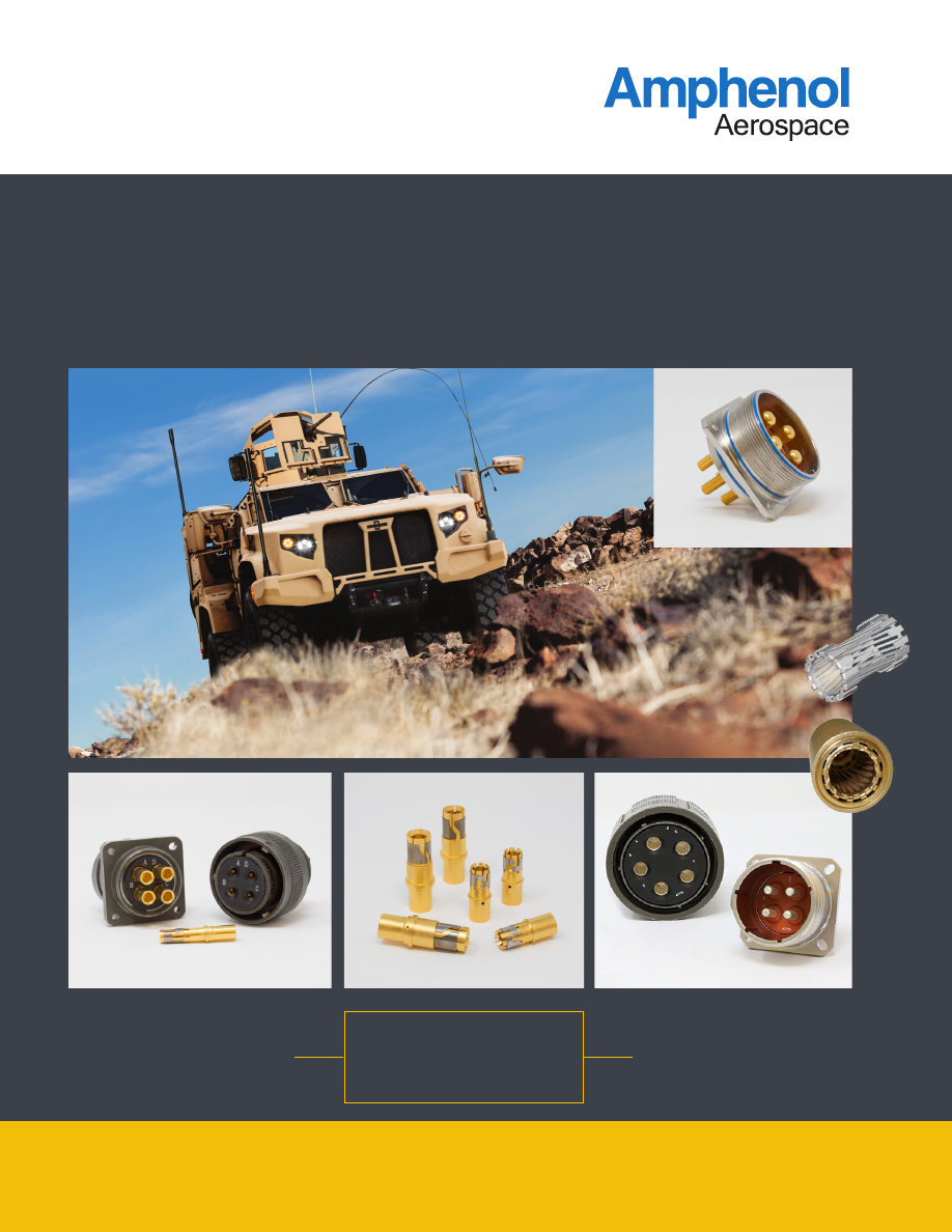
background image

High 

POWER

For High Current and High Temperature Environments

CONNECTORS

38999  

Tri-Power

5015 

Power

RADSOK 

Temper-GRIP

Contacts

Amphenol-HighPower-Connectors-html.html
background image

Customer-Centric:

Customer-Centric:


Our 

#1 priority

 is our customers who 

deserve quality product on time.

CARE

Accountable:


Clear owners, clear  

actions, clear results.

Reliable:


What we build 
matters and quality 
is imperative.

Enthusiastic:


Challenges create rewarding 
opportunities. Enthusiasm is 
contagious and we will spread it.

Quality Assurance:

Amphenol Aerospace has been awarded 
both AS9100 - Revision C and ISO9001:2008 
Quality Assurance Certifications.

Amphenol-HighPower-Connectors-html.html
background image

Contact Amphenol Aerospace for more information at 800-678-0141  •  www.amphenol-aerospace.com

3

Table of Contents

Table of Contents  
 

Contacts

High Power 5015

High Power Series Introduction ..........................  4
Class Descriptions, Performance Specifications .  5
High Power Contacts .........................................  6
High Power Heat Rise Test Data .........................    7
We Recommend Temper Grip ............................  8
Thread Chart and Termination Diameters ............  9 
Male Threaded Termination ................................  10
Female Thread Termination ................................  11
Solder Cup and PCB Termination .......................  12
Insert Availability and Identification  .....................  13
Insert Arrangements ..........................................  14-15
Insert Alternate Positioning .................................  16
How to Order .....................................................  17
Straight Plug ......................................................  18
Wall Mounting Receptacle ..................................  19
Jam Nut Receptacle ..........................................  20
Box Mounting Receptacle ..................................  21 
Contact Information, Sealing Plugs, Tools ...........  22

Tri-Power 38999

Tri-Power Introduction ........................................  23 
Tri-Power How-to-Order ....................................  24
MP07/TV07 Jam Nut Receptacle .......................  25
MP06/TV06 Plug ...............................................  26 
MP00/TV00 Wall Mount Receptacle ...................  27

Accessories .......................................................  28

Amphenol-HighPower-Connectors-html.html
background image

Contact Amphenol Aerospace for more information at 800-678-0141  •  www.amphenol-aerospace.com

4

POWER 5015


Step files available for most configurations in under 48 hours! 


High Power 5015 Series Introduction

Models and drawings available online at 
www.amphenol-aerospace.com by 
selecting the configurator tool.

Amphenol has revolutionized its standard power 
connector offerings with advanced contact technology 
and new contact termination methods resulting in 
unrivaled catalog customization.

Utilizing two proven connector interfaces  
(Matrix 5015 and GT-5015) and a host of tooled insert 
arrangements, Amphenol has a connector for every 
high power application.

DESIGN CHARACTERISTICS

•  40-50% increased current carrying capability over ` 
    standard 5015 connector
•  Threaded or bayonet coupling available
•  Catalog customization reduces design-in time
•  Standard interfaces allow users to utilize existing  
  cabling design where high performance is needed
•  Gold plated contacts mean higher performance in  
  demanding environments

CUSTOMER OPTIONS

•  Contact termination methods including crimp, male  
  and female threaded termination, solder, PCB and  
 bus-bar
•  Epoxy backfilled options for increased  
  environmental performance where needed
•  Socket contact options include the low resistance  
  RADSOK® technology and Amphenol’s new  


  TEMPER-GRIP contact for high current carrying   
  capability at over 200°C
•  Over 25 tooled insert arrangements for current    
  carrying capacity from 50 to nearly 1000 amps per  
 connector
•  Standard and proprietary plating options including  
  Durmalon, Amphenol’s Nickel Teflon plating which  
  is RoHS/Reach compliant and can handle 500    
  hours of salt spray exposure
•  Customizable - If you require any special  
  mechanical or  electrical configurations that are not  
  listed within, please contact the factory for a  


  quick-turn custom design 

APPLICATIONS

•  Hybrid-drive/electric vehicles
•  Laser power systems
•  Ruggedized power converters
•  And many more

Male threaded post termination PKT02RFM36-5P

Shown Left: Box mount with solder cup contacts 
PKB02RWP22-22P  
Shown Right: Plug with crimp removable  
Temper-Grip Contacts PKB06RWC22-22T

Amphenol-HighPower-Connectors-html.html
background image

Contact Amphenol Aerospace for more information at 800-678-0141  •  www.amphenol-aerospace.com

POWER 5015

5

Class Descriptions, Performance Specifications

VOLTAGE RATING/SERVICE RATING

Altitude

Inst.

A

D

E

B

C

Sea Level

1000

2000

2800

3500

4500

7000

50,000 ft.

400

600

675

750

825

975

70,000 ft.

260

360

400

440

480

560

110,000 ft.

200

200

200

200

200

200

PERFORMANCE SPECIFICATIONS

CLASS DESCRIPTIONS

SHOCK

Wired, mated connectors are subjected to one shock in each of three 
mutu ally perpendicular axes with pulse of an approximate half sine wave of 
50g magnitude  
for a duration of 11 milliseconds. All contacts wired in series cir cuit with 100 
±10 Milliamperes of current flow.

OPERATING TEMPERATURE RANGE

Classes RF, RL, and RK have temperature range of 

–55°C (–75°F) to 200°C (392°F) 

Classes RW, DT, & DZ have temperature range of 

–55°C (–75°F) to 175°C (347°F)

ENVIRONMENTAL SEAL

Wired, mated connectors with environmental accessories  
attached as required, will meet the altitude immersion test  
specified in MIL-DTL-5015. Backfilled connector options offer 
 increased sealing in the unmated condition.

DURABILITY

Minimum of 100 mating cycles. For  higher durability RADSOK

®


contacts are recommended.

Military

Finish

RoHS

Material/ Description

RF

Electroless Nickel

Ro

HS

Am

phenol

EU

/ 2002 / 95 /

EC

Aluminum, 200°C*, 48 hour salt spray

RK

Passivated Stainless Steel

Ro

HS

Am

phenol

EU

/ 2002 / 95 /

EC

200°C*, 500 hour salt spray resistance

RL

Stainless Steel w/ Nickel Plate

Ro

HS

Am

phenol

EU

/ 2002 / 95 /

EC

Corrosion resistant steel, 200°C*, 500 hour salt spray

RW

Olive Drab Cadmium

Aluminum, 175°C* , 500 hour salt spray

DT

Durmalon plated

Ro

HS

Am

phenol

EU

/ 2002 / 95 /

EC

Nickel-PTFE alternative to Cadmium, 175°C*, 500 

hour salt spray 

DZ

Zinc-Nickel Plated

Ro

HS

Am

phenol

EU

/ 2002 / 95 /

EC

Zinc-Nickel Alternative to Cadmium, 175°C*, 500 

hour salt spray (Not available in size 36)

DW

Thick Olive Drab Cadmium

Thick O.D. CAD, 175°C* , 500 hour salt spray

*Utilizing the Temper-Grip sockets

Amphenol-HighPower-Connectors-html.html
background image

Contact Amphenol Aerospace for more information at 800-678-0141  •  www.amphenol-aerospace.com

6

HIGH POWER CONT

ACTS

•  Fully interchangable with M39029 pins
•  Available in any Amphenol connector series*
•  10%-20% improved ampacity

FEATURES AND BENEFITS:

Replacing your contacts with HCP contacts will improve 
your performance, but you can improve your performance 
even more by replacing your sockets too. Using 
Temper-Grip sockets with HCP contacts provides a viable 
solution for applications up to 220’C. Heat rise data for 
HCP contacts used with Temper-Grip sockets is listed on 
the following page. 

Amphenol is now offering high current pins that can be ordered with any Amphenol connector.

Using high conductivity alloys and precision machining Amphenol has developed a high current pin to reduce 
power loss in your application. Push the current carrying capability past the limits of a Mil-Spec contact, or simply 
improve the efficiency of your system while reducing the heat dissipated into your platform.

High Current Pin Contacts

Amphenol-HighPower-Connectors-html.html
background image

Contact Amphenol Aerospace for more information at 800-678-0141  •  www.amphenol-aerospace.com

HIGH POWER CONT

ACTS

7

Heat rise data shows performance of HCP (High Current Pins) compared to standard mil-spec pins and sockets. 
HCP sizes 0,4, and 8 are mated with Temper-Grip Sockets. Smaller Temper-Grip contacts are under development 
(contact factory for more information), so HCP sizes 12 & 16 were mated with a standard 39029 socket.

HCP with Temper-Grip

HCP with Standard 39029 Sockets

High Current Pin Heat Rise Testing Data

Amphenol-HighPower-Connectors-html.html
background image

Contact Amphenol Aerospace for more information at 800-678-0141  •  www.amphenol-aerospace.com

8

HIGH POWER CONT

ACTS

LOW CONTACT ENGAGEMENT/SEPARATION FORCES

The hyperbolic lamella socket contact construction distributes 
normal forces over a high percentage of mating pin surface. This 
creates a smooth, even engagement effort. This force distribution 
also contributes to excellent performance in vibration applications 
with resistance to typical fretting corrosion.

LOW CONTACT RESISTANCE

The large interface area between the socket lamella and pin 
surface results in very low contact resistance, enabling the  
RADSOK

®

 contacts’ high current rating compared to traditional 

power contact designs. 

HIGH MATING CYCLE DURABILITY

RADSOK contacts with typical silver plating finishes have  
demonstrated survival of 20,000 mating cycles. Even with  
continuous exposure to harsh environmental abuse (salt, sand, 
and high humidity). RADSOK contacts have been tested to 
maintain low contact resistance beyond 10,000 mating cycles. 

HIGH TEMPERATURE CAPABILITY

For use in high temperature (200 C+) applications, 
the Temper-grip socket has been tested to maintain 
current capability in high temperature situations 
where standard mil-spec socket contacts can begin 
to relax.

“NAPKIN-RING” TECHNOLOGY

Proven design utilizing a stainless steel napkin ring 
to prevent the beryllium copper tines from “relaxing” 
at higher temperatures and maintaining a greater  
area of true contact in all situations to  
decrease resistance.

TEMPER-

GRIP

Standard 

Contacts

RADSOK Contacts

Size

Amps

Size

Amps

Cartridgesize

8

46

8

70

3.6 MM

4

80

4

120

5.7MM

0

150

0

250

9.1MM

Standard 

Contacts

Temper-GRIP

Contacts

Size

Amps

Size

Amps

8

46

8

65

4

80

4

110

0

150

0

220

RADSOK

We Recommend Temper-Grip with High Current Pin Contacts

Socket Contact Options

Amphenol-HighPower-Connectors-html.html
background image

Contact Amphenol Aerospace for more information at 800-678-0141  •  www.amphenol-aerospace.com

POWER 5015

9

Thread Chart and Termination Diameters

THREAD CHART AND TERMINATION DIAMETERS

Contact 

Size

Thread Type

Solder 

Cup

PC Tail

Male

Female

Thread 

Wrench Flat 

“AM”

Thread

Wrench 

Flat “AF”

Diameter                 

B

Diameter         

D

16

*

*

*

*

0.078

0.062

12

*

*

*

*

0.116

0.081

8

#5-44-UNF

0.200

#8-32-UNF

0.220

0.209

0.142

4

#10-32-UNF

0.300

#12-28-UNF

0.320

0.332

0.225

0

1/4-28-UNF

0.450

5/16-24-UNF

0.480

0.469

0.356

*Except for PC tail and Busbar, Size 12 and 16 contacts are solder cup for backfilled connectors, 
crimp for non-backfilled connectors.  

CONTACT FACTORY FOR 
BUS BAR TERMINATION OPTIONS

ALL DIMENSIONS SHOWN ARE FOR POTTED CONNECTOR VERSIONS AND ARE MEASURED FROM
THE BACK OF THE CONNECTOR SHELL. IF NEEDED, FOR CONNECTORS WITH NON-POTTED CONTACTS, 
CONTACT FACTORY FOR ANY APPLICABLE STICKOUT

ØD

ØD

AM

AF

L

L

L

L

F

ØB

ØB

SEE THREAD 
TABLE

SEE THREAD 
TABLE

SOLDER CUP

FEMALE THREAD

TERMINATION

MALE THREAD

TERMINATION

PC TAIL

BUSBAR/LUG

ØG

ØE

AB

L

For more options or 

custom requirements, 

contact factory

All dimensions are nominal, contact Amphenol for exact tolerances. For PKB05 dimensions, contact factory

BUSBAR CHART

Contact Size

ØE

ØG

AB

L

8

.100

.263

.100

4

.190

.375

.200

1.100” max

0

.250

.563

.250

All sizes

Amphenol-HighPower-Connectors-html.html
background image

Contact Amphenol Aerospace for more information at 800-678-0141  •  www.amphenol-aerospace.com

10

POWER 5015

MALE THREADED TERMINATION *

Shell 

Size

PKT

PKT00

PKT02

PKT05

PKT06

PKT07

L

F

L

F

L

F

L

F

L

F

16

0.750 0.200 0.812 0.262 0.740 0.190 0.740 0.190 0.750 0.200

18

0.700 0.150 0.801 0.251 0.670 0.120 0.670 0.120 0.700 0.150

20

0.700 0.150 0.801 0.251 0.670 0.120 0.670 0.120 0.700 0.150

22

0.700 0.150 0.793 0.243 0.670 0.120 0.670 0.120 0.700 0.150

24

0.685 0.135 0.793 0.243 0.670 0.120 0.670 0.120 0.685 0.135

28

0.685 0.135 0.793 0.243 0.670 0.120 0.670 0.120 0.685 0.135

32

0.685 0.135 0.845 0.295 0.670 0.120 0.670 0.120 0.685 0.135

36

0.685 0.135 0.793 0.243 0.670 0.120 0.670 0.120 0.685 0.135

*Dimensions are measured from back of shell

MALE THREADED TERMINATION*

Shell 

Size

PKB

PKB00

PKB02

PKB06

PKB07

PKB08

L

F

L

F

L

F

L

F

L

F

16

0.808 0.258 0.808 0.258 0.795 0.245 0.687 0.137 0.804 0.254

18

0.808 0.258 0.808 0.258 0.795 0.245 0.81

0.26 0.772 0.222

20

0.808 0.258 0.808 0.258 0.795 0.245 0.81

0.26 0.772 0.222

22

0.808 0.258 0.808 0.258 0.795 0.245 0.81

0.26 0.772 0.222

24

0.733 0.183 0.733 0.183 0.732 0.182 0.81

0.26

0.76

0.21

28

0.733 0.183 0.733 0.183 0.732 0.182 0.72

0.17

0.67

0.12

32

0.67

0.12

0.67

0.12

0.67

0.12

0.72

0.17

0.67

0.12

36

0.67

0.12

0.67

0.12

0.67

0.12

0.72

0.17

0.67

0.12

*Dimensions are measured from back of shell

For more options or 

custom requirements, 

contact factory

All dimensions are nominal, contact Amphenol for exact tolerances. For PKB05 dimensions, contact factory

Male Threaded Termination

CONTACT FACTORY FOR 
BUS BAR TERMINATION OPTIONS

ALL DIMENSIONS SHOWN ARE FOR POTTED CONNECTOR VERSIONS AND ARE MEASURED FROM
THE BACK OF THE CONNECTOR SHELL. IF NEEDED, FOR CONNECTORS WITH NON-POTTED CONTACTS, 
CONTACT FACTORY FOR ANY APPLICABLE STICKOUT

ØD

ØD

AM

AF

L

L

L

L

F

ØB

ØB

SEE THREAD 
TABLE

SEE THREAD 
TABLE

SOLDER CUP

FEMALE THREAD

TERMINATION

MALE THREAD

TERMINATION

PC TAIL

BUSBAR/LUG

ØG

ØE

AB

L

Amphenol-HighPower-Connectors-html.html
background image

Contact Amphenol Aerospace for more information at 800-678-0141  •  www.amphenol-aerospace.com

POWER 5015

11

Female Thread Termination

FEMALE THREADED TERMINATION *

Shell 

Size

PKT

PKB

PKT00 PKT02 PKT05 PKT06 PKT07 PKB00 PKB02 PKB06 PKB07 PKB08

L

L

L

L

L

L

L

L

L

L

16

0.300

0.362

0.290

0.290

0.300

0.358

0.358

0.345

0.237

0.354

18

0.250

0.351

0.220

0.220

0.250

0.358

0.358

0.345

0.360

0.322

20

0.250

0.351

0.220

0.220

0.250

0.358

0.358

0.345

0.360

0.322

22

0.250

0.343

0.220

0.220

0.250

0.358

0.358

0.345

0.360

0.322

24

0.235

0.343

0.220

0.220

0.235

0.283

0.283

0.282

0.360

0.310

28

0.235

0.343

0.220

0.220

0.235

0.283

0.283

0.282

0.270

0.220

32

0.235

0.395

0.220

0.220

0.235

0.220

0.220

0.220

0.270

0.220

36

0.235

0.343

0.220

0.220

0.235

0.220

0.220

0.220

0.270

0.220

*Dimensions are measured from back of shell

For more options or 

custom requirements, 

contact factory

All dimensions are nominal, contact Amphenol for exact tolerances. For PKB05 dimensions, contact factory

CONTACT FACTORY FOR 
BUS BAR TERMINATION OPTIONS

ALL DIMENSIONS SHOWN ARE FOR POTTED CONNECTOR VERSIONS AND ARE MEASURED FROM
THE BACK OF THE CONNECTOR SHELL. IF NEEDED, FOR CONNECTORS WITH NON-POTTED CONTACTS, 
CONTACT FACTORY FOR ANY APPLICABLE STICKOUT

ØD

ØD

AM

AF

L

L

L

L

F

ØB

ØB

SEE THREAD 
TABLE

SEE THREAD 
TABLE

SOLDER CUP

FEMALE THREAD

TERMINATION

MALE THREAD

TERMINATION

PC TAIL

BUSBAR/LUG

ØG

ØE

AB

L

Amphenol-HighPower-Connectors-html.html
background image

Contact Amphenol Aerospace for more information at 800-678-0141  •  www.amphenol-aerospace.com

12

POWER 5015

PCB TERMINATION 

Shell 

Size

PKT

PKB

PKT00

PKT02 PKT05

PKT06

PKT07 PKB00 PKB02

PKB06

PKB07

L

L

L

L

L

L

L

L

L

16

0.750

0.812

0.740

0.740

0.750

0.808

0.608

0.595

0.687

18

0.700

0.801

0.670

0.670

0.700

0.808

0.608

0.595

0.810

20

0.700

0.801

0.670

0.670

0.700

0.808

0.608

0.595

0.810

22

0.700

0.793

0.670

0.670

0.700

0.808

0.608

0.595

0.810

24

0.685

0.793

0.670

0.670

0.685

0.733

0.533

0.532

0.810

28

0.685

0.793

0.670

0.670

0.685

0.733

0.533

0.532

0.720

32

0.685

0.845

0.670

0.670

0.685

0.670

0.470

0.470

0.720

36

0.685

0.793

0.670

0.670

0.685

0.670

0.470

0.470

0.720

*Dimensions are measured from back of shell

SOLDER CUP TERMINATION (BACK FILL)

Shell 

Size

PKT

PKB

PKT00

PKT02

PKT05

PKT06

PKT07

PKB00

PKB02

PKB06

PKB07

L

L

L

L

L

L

L

L

L

16

0.230

0.292

0.220

0.220

0.230

0.288

0.288

0.275

0.167

18

0.180

0.281

0.150

0.150

0.180

0.288

0.288

0.275

0.29

20

0.180

0.281

0.150

0.150

0.180

0.288

0.288

0.275

0.29

22

0.180

0.273

0.150

0.150

0.180

0.288

0.288

0.275

0.29

24

0.165

0.273

0.150

0.150

0.165

0.213

0.213

0.212

0.29

28

0.165

0.273

0.150

0.150

0.165

0.213

0.213

0.212

0.2

32

0.165

0.325

0.150

0.150

0.165

0.15

0.15

0.15

0.2

36

0.165

0.273

0.150

0.150

0.165

0.15

0.15

0.15

0.2

*Dimensions are measured from back of shell

All dimensions are nominal, contact Amphenol for exact tolerances. For PKB05 dimensions, contact factory

For more options or 

custom requirements, 

contact factory

Solder Cup and PCB Termination

CONTACT FACTORY FOR 
BUS BAR TERMINATION OPTIONS

ALL DIMENSIONS SHOWN ARE FOR POTTED CONNECTOR VERSIONS AND ARE MEASURED FROM
THE BACK OF THE CONNECTOR SHELL. IF NEEDED, FOR CONNECTORS WITH NON-POTTED CONTACTS, 
CONTACT FACTORY FOR ANY APPLICABLE STICKOUT

ØD

ØD

AM

AF

L

L

L

L

F

ØB

ØB

SEE THREAD 
TABLE

SEE THREAD 
TABLE

SOLDER CUP

FEMALE THREAD

TERMINATION

MALE THREAD

TERMINATION

PC TAIL

BUSBAR/LUG

ØG

ØE

AB

L

Amphenol-HighPower-Connectors-html.html
background image

Contact Amphenol Aerospace for more information at 800-678-0141  •  www.amphenol-aerospace.com

POWER 5015

13

Insert Availability and Identification 

Insert 

Arrangement

Service 

Rating

Total 

Contacts

Contact Size

0

4

8

12

16

16-12

A

1

1

18-13

A

4

1

3

20-2

D

1

1

20-8

Inst.

6

2

4

20-14

A

5

2

3

20-19

A

3

3

20-22

A

6

3

3

22-2

D

3

3

22-6*

D

3

2

1

22-7*

E

1

1

22-21

A

3

1

2

22-22

A

4

4

24-10

A

7

7

24-11

A

9

3

6

24-12

A

5

2

3

24-22

D

4

4

28-1

D/A

9

3

6

28-10

D/A

7

2

2

3

28-22

D

6

3

3

32-1

E/D

5

2

3

32-9

D

14

2

12

32-15

D

8

2

6

32-17

D

4

4

36-3

D

6

3

3

36-5

A

4

4

36-6

A

6

2

4

36-9

A

31

1

2

14

14

Amphenol-HighPower-Connectors-html.html
background image

Contact Amphenol Aerospace for more information at 800-678-0141  •  www.amphenol-aerospace.com

14

POWER 5015

Insert Arrangement

16-12

18-13

20-2

20-8

20-14

20-19†

20-22

Service Rating

A

A

D

Inst.

A

A

A

Number of Contacts

1

1

3

1

2

4

2

3

3

3

3

Contact Size

4

8

12

0

8

16

8

12

8

8

16

F

ront Face of Pin Insert or Rear Face of Socket Insert Illustrated

† Designates arrangements suitable for bussing multiple contacts together for increased current carrying capability. Contact 
factory for more information.

Insert Arrangements

CONTACT LEGEND 

16 

12 

0

A

B

C

D

A

B

C

D

E

F

A

B

C

D

E

A

B

C

A

B

C

D

E

F

A

B

C

Insert Arrangement

22-2†

22-6

22-7

22-21

22-22†

24-10

Service Rating

D

D

E

A

A

A

Number of Contacts

3

2

1

1

1

2

4

7

Contact Size

8

8

16

0

0

16

8

8

A

B

C

A

B

C

A

B

C

D

A

B

C

D

E

F

G

A

B

C

D

E

F

G

H

I

A

B

C

D

E

Insert Arrangement

24-11

24-12

24-22†

28-1

28-10

Service Rating

A

A

D

A, J, E = D; Bal. = A

G = D, Bal. = A

Number of Contacts

3

6

2

3

4

3

6

2

2

3

Contact Size

8

12

4

12

8

8

12

4

8

12

A

B

C

D

A

B

C

D

E

F

G

H

J

A

B

C

D

E

F

G

Amphenol-HighPower-Connectors-html.html
background image

Contact Amphenol Aerospace for more information at 800-678-0141  •  www.amphenol-aerospace.com

POWER 5015

15

A

B

C

D

E

A

B

C

D

E

F

G

H

I

J

K

L

M

N

A

B

C

D

E

F

G

H

Insert Arrangement

28-22†

32-1†

32-9

Service Rating

D

A = E; B, C, D, E 

= D

D

Number of Contacts

3

3

2

3

2

12

Contact Size

4

16

0

12

4

16

A

B

C

D

A

B

C

D

E

F

A

B

C

D

A

B

C

D

E

F

A

B

C

D

E

F

G

H

I

J

K

L

M

N

O

P

R

S

T

U

V

W

X

Y

Z

a

b

c

d

e

f

Insert Arrangement

32-15†

32-17†

36-3†

Service Rating

D

D

D

Number of Contacts

2

6

4

3

3

Contact Size

0

12

4

0

12

F

ront Face of Pin Insert or Rear Face of Socket Insert Illustrated

Insert Arrangements

Insert Arrangement

36-5†

36-6†

36-9

Service Rating

A

A

A

Number of Contacts

4

2

4

1

2

14

14

Contact Size

0

0

4

4

8

12

16

A

B

C

D

E

F

CONTACT LEGEND 

16 

12 

0

Amphenol-HighPower-Connectors-html.html
background image

Contact Amphenol Aerospace for more information at 800-678-0141  •  www.amphenol-aerospace.com

16

POWER 5015

To avoid cross-plugging problems in applications requiring 
the use of more than one connector of the same size and  
arrangement, alternate rotations are available as indicated  
in the accompanying charts.

As shown in the diagram below, the front face of the pin 
insert is rotated within the shell in a clockwise direction 
from the normal shell key. The socket insert would be 
rotated counter-clockwise the same number of degrees in 
respect to the normal shell key.

The charts give the W, X, Y, Z positions for the alternate 
rotations available for the insert arrangements of the rear 
release  
MIL-DTL-5015 series of connectors. If an insert arrange-
ment number is not given, then there is no available 
alternate rotation for that pattern.

A

B

A

B

A

B

A

B

Insert Alternate Positioning

Position W            Position X       Position Y         Position Z

View looking into front face of pin insert or rear of socket insert.

Arrangement

Degrees

W

X

Y

Z

16-12

Alternates Not Available

18-13

80

110

250

280

20-2

Alternates Not Available

20-8

80

110

250

280

20-14

80

110

250

280

20-19

90

180

270

-

20-22

80

110

250

280

22-6

80

110

250

280

22-7

Alternates Not Available

22-2

70

145

215

290

22-21

80

110

250

280

22-22

-

110

250

-

24-10

80

-

-

280

24-11

35

110

250

325

24-12

80

110

250

280

24-22

45

110

250

-

28-1

80

110

250

280

32-1

80

110

250

280

32-9

80

110

250

280

32-15

35

110

250

280

32-17

45

110

250

-

36-3

70

145

215

290

36-5

-

120

240

-

36-6

35

110

250

325

36-9

80

125

235

280

Amphenol-HighPower-Connectors-html.html
background image

Contact Amphenol Aerospace for more information at 800-678-0141  •  www.amphenol-aerospace.com

POWER 5015

17

How to Order

High Power Series

1.

2.

3.

4.

5.

6.

7.

Connector 

Type

Shell 

Style

Finish

Contact Style

Shell Size– 

Insert Arrangement

Socket 

type/Pin

Alternate 

Positions

PKB

00

DT

M

28–22

R

W

2. SHELL STYLE 

00

Wall mount receptacle

02

Box mount receptacle

05

Straight Plug with rear access (PKB only)

06

Straight plug

07

Jam Nut Receptacle

08

Jam Nut Receptacle with rear accessory threads  

(PKB ONLY)

09

Self-locking plug (PKT ONLY)

3. FINISH

DT

Durmalon (PTFE)

DZ

Black Zinc Nickel

RF

Electroless Nickel

RW

O.D. CAD

RL

Nickel Plating Stainless Steel

RK

Passivated Stainless Steel

DW

Thick O.D. CAD

*Contact factory for custom plating options

6. SOCKET TYPE / PIN

SOCKET

T

Temper-Grip- Recommended for 150°C +

R

RADSOK- Recommended up to 150°C

S

Standard Socket Contacts

PIN

P

Pin

1. CONNECTOR TYPE

PKB

High power with bayonet coupling

PKT

High power with threaded coupling

4. CONTACT STYLE

M

Male Thread Termination (Potted-in)

F

Female Thread Termination (Potted-in)

C

Crimp (removable with grommet)*

S

Solder (removable with grommet)*

P

Solder (potted-in)

B

Busbar (contact factory for details)

T

PC Tail (Potted-in)

Note-All size 12 & 16 contacts are solder cup except for 

“C” class which are crimp & “T” class which are PC Tail

* Box mounts don’t include grommet

For more information on Busbar versions,  

contact factory

5. SHELL SIZE & INSERT ARRANGEMENT

PAGE 

13-14 

First number represents Shell Size,  

second number is the Insert Arrangement.

7. ALTERNATE POSITIONS

“W”, “X”, “Y”, “Z” designate that insert is rotated in its 
shell from normal position. No letter required for normal 
(no rotation) position. See page 13 for description of 
alternate positions.

Amphenol-HighPower-Connectors-html.html
background image

Contact Amphenol Aerospace for more information at 800-678-0141  •  www.amphenol-aerospace.com

18

POWER 5015

Polarizing Keyway

Blue Color Band

H Accessory Thread

J Coupling
Thread

3 Teeth
Equally Spaced
120  Apart

D Min. Full
Thread

C Max.

B

Dia.

E

Dia

Max.

A

Dia Max.

˚

Shell 

Size

Dia. 

Max.

Dia. 

±.005

C Max.

Min.

Dia. 

Max.

Thread 

Class 2A

Thread 

Class 2B

16

1.250

 .800

2.500

.290

.790

1.0000-20 UNEF

1.0000-20 UNEF

18

1.344

 .925

2.500

.290

.869

1.0625-18 UNEF

1.1250-18 UNEF

20

1.469

1.045

2.500

.290

.994

1.1875-18 UNEF

1.2500-18 UNEF

22

1.594

1.170

2.500

.290

1.119

1.3125-18 UNEF

1.3750-18 UNEF

24

1.719

1.295

2.500

.290

1.244

1.4375-18 UNEF

1.5000-18 UNEF

28

1.969

1.515

2.500

.467

1.465

1.7500-18 UNS

1.7500-18 UNS

32

2.219

1.765

2.500

.467

1.715

2.0000-18 UNS

2.0000-18 UNS

36

2.469

1.975

2.500

.467

1.930

2.2500-16 UN

2.2500-16 UN

Straight Plug

PKB05, PKB06, PKT06, and PKT09

Shell 

Size

Thread 

Class 2A

C Thread  

Class 2A

Ref

L1 Ref

C Max

Q

Max

16†

1.0000-20 UNEF

-

-

-

2.500

1.260

18†

1.0625-18 UNEF

-

-

-

2.500

1.437

20†

1.1875-18 UNEF

-

-

-

2.500

1.571

22†

1.3125-18 UNEF

-

-

-

2.500

1.697

24

1.4375-18 UNEF

1.4375-18 UNEF

1.095

2.389

2.500

1.835

28

1.7500-18 UNS

1.4375-18 UNEF

1.229

2.489

2.500

2.102

32

2.0000-18 UNS

1.7500-18 UNS

1.489

2.539

2.500

2.366

36

2.2500-16 UN

2.0000-18 UNS

1.781

2.589

2.500

2.610

† Not available in PKB05

PKB05 & 

PKB06            

PKT06  

PKT09       


PKB06  

(WITHOUT  REAR  ACCESSORY)             

Q

C

F

L1

B

C MAX

PKB05  

(WITH REAR ACCESSORY)


Amphenol-HighPower-Connectors-html.html
background image

Contact Amphenol Aerospace for more information at 800-678-0141  •  www.amphenol-aerospace.com

POWER 5015

19

H Accessory Thread

3 Teeth Equally
Placed 120  Apart

Blue Color Band

E Dia.

Max

G Min. Full
Thread

J Coupling
Thread

D Max.

F

K

Polarizing 
Key

A Typ.

B Typ.

B Typ.

PANEL CUTOUT

C Dia.
4 Holes

C Dia.

L Dia.

°

Shell 

Size

±.031

B

C Dia. 

+.010 

–.005

D Max.

Dia. 

Max.

F

Min.

Thread 

Class 2A

Thread 

Class 2A

K

Dia. 

±.010

Class 

A, F, R, 

W

Class 

K

16

1.281

.969

.120

.150

2.500

.790

.781/.750 .290

1.0000-20 UNEF

1.0000-20 UNEF

.083 1.062

18

1.375

1.062

.120

.177

2.500

.869

.781/.750 .290

1.0625-18 UNEF

1.1250-18 UNEF

.125 1.188

20

1.500

1.156

.120

.177

2.500

.994

.781/.750 .290

1.1875-18 UNEF

1.2500-18 UNEF

.125 1.312

22

1.625

1.250

.120

.177

2.500

1.119 .781/.750 .290

1.3125-18 UNEF

1.3750-18 UNEF

.125 1.438

24

1.750

1.375

.147

.177

2.500

1.244 .843/.812 .290

1.4375-18 UNEF

1.5000-18 UNEF

.125 1.562

28

2.000

1.562

.147

.177

2.500

1.465 .843/.812 .467

1.7500-18 UNS

1.7500-18 UNS

.125 1.812

32

2.250

1.750

.173

.209

2.500

1.715 .906/.875 .467

2.0000-18 UNS

2.0000-18 UNS

.125 2.062

36

2.500

1.938

.173

.209

2.500

1.930 .906/.875 .467

2.2500-16 UN

2.2500-16 UN

.125 2.312

Wall Mounting Receptacle

PKB00 & PKT00                      

Shell 

Size

Thread 

Class 2A

±.010

+.016 

–.000

+.000 

–.006

±.008

±.004

±.012

+.004 

–.000

16

1.0000-20 UNEF

1.575

.846

1.079

.126

.969

1.280

.126

18

1.0625-18 UNEF

1.623

.907

1.213

.157

1.063

1.378

.126

20

1.1875-18 UNEF

1.623

.907

1.346

.157

1.157

1.496

.126

22

1.3125-18 UNEF

1.623

.907

1.472

.157

1.252

1.614

.126

24

1.4375-18 UNEF

1.638

.907

1.610

.157

1.374

1.752

.146

28

1.7500-18 UNS

1.638

.947

1.839

.157

1.563

2.000

.146

32

2.0000-18 UNS

1.638

.947

2.102

.157

1.752

2.244

.169

36

2.2500-16 UN

1.638

.947

2.346

.157

1.937

2.500

.169

PKB00


PKT00 


R

R

S

T

82º

T

R

R

S

S

82º

T

N

M

P

L

B

Amphenol-HighPower-Connectors-html.html
background image

Contact Amphenol Aerospace for more information at 800-678-0141  •  www.amphenol-aerospace.com

20

POWER 5015

PANEL CUTOUT

Blue Color
Band

J Coupling
Thread

Pin Protrusion

A Typ.

.045
.035

.180
.165

.128 Max.
Panel Thickness

G
Min. Full Thread

3 Teeth
Equally Spaced
120  Apart

H Accessory
Thread

.100
.095

.196
.186

M

Dia.

C

Dia.

B

Typ.

E

Dia

Max.

Polarizing
Key

L

D Max

F

O-Ring

°

Shell 

Size

±.010

±.005

Dia. 

±.005

D Max.

Dia. 

Max.

±.005

Min.

Thread 

Class 2A

Thread 

Class 2A

Panel Cutout 

Dimensions

±.005

M Dia. 

+.015 

–.000

16

1.250

1.687

1.772

2.500

.790

.970

.290

1.0000-20 UNEF

1.0000-20 UNEF

.573

1.005

18

1.375

1.812

1.897

2.500

.869

.970

.290

1.0625-18 UNEF

1.1250-18 UNEF

.635

1.130

20

1.500

1.937

2.022

2.500

.994

.970

.290

1.1875-18 UNEF

1.2500-18 UNEF

.698

1.255

22

1.625

2.156

2.241

2.500

1.119

.970

.290

1.3125-18 UNEF

1.3750-18 UNEF

.760

1.380

24

1.750

2.281

2.366

2.500

1.244

.970

.290

1.4375-18 UNEF

1.5000-18 UNEF

.823

1.505

28

2.000

2.531

2.616

2.500

1.465

.970

.467

1.7500-18 UNS

1.7500-18 UNS

.948

1.755

32

2.375

2.781

2.866

2.500

1.715

.970

.467

2.0000-18 UNS

2.0000-18 UNS

1.073

2.005

36

2.625

3.031

3.116

2.500

1.930

.970

.467

2.2500-16 UN

2.2500-16 UN

1.198

2.255

Jam Nut Receptacle

PKB07 & PKT07

Shell 

Size

Thread 

Class 2A

±.012

J  

Wall Thickness

±.010

±.012

+.000 

–.006

±.007

±.016

±.012

BB 

Thread Class 2A

Min.

Max.

16

1.2500-18 UNEF

.618

.094

.295

1.909

1.264

1.079

.189

1.500

1.748

1.0000-20 UNEF

18

1.3750-18 UNEF

.661

.094

.354

1.941

1.327

1.213

.189

1.562

1.875

1.1250-18 UNEF

20

1.5000-18 UNEF

.709

.094

.358

1.941

1.327

1.349

.189

1.750

2.000

1.2500-18 UNEF

22

1.6250-18 UNEF

.795

.094

.358

1.941

1.327

1.472

.189

2.000

2.134

1.3750-18 UNEF

24

1.7500-18 UNEF

.795

.094

.358

1.953

1.327

1.610

.189

2.000

2.252

1.6250-18 UNEF

28

2.0000-18 UNEF

.886

.094

.394

2.043

1.386

1.839

.220

2.188

2.500

1.8750-16 UN

32

2.2500-16 UN

.972

.094

.394

2.043

1.386

2.102

.220

2.438

2.748

2.0625-16 UN

36

2.5000-16 UN

1.059

.094

.327

2.043

1.386

2.346

.220

2.812

3.000

2.3125-16 UN

PKB07  


PKT07  


N

M

P

B

O-Ring

BB

L

J

G

S

S

G

R

Amphenol-HighPower-Connectors-html.html
background image

Contact Amphenol Aerospace for more information at 800-678-0141  •  www.amphenol-aerospace.com

POWER 5015

21

Blue Color Band

E Dia.

Max

J Coupling
Thread

D Max.

F

G

Polarizing 
Key

A Typ.

B Typ.

B Typ.

PANEL CUTOUT

C Dia.
4 Holes

C Dia.

L Dia.

Shell 

Size

±.031

B

Dia.

D Max.

Dia. 

±.016

F

±.015

Thread 

Class 2A

Dia. 

±.010

16

1.281

.969

.130/.115

1.937

1.000

.765/.750

.083

1.0000-20 UNEF

1.062

18

1.375

1.062

.130/.115

1.937

1.062

.765/.750

.125

1.1250-18 UNEF

1.188

20

1.500

1.156

.130/.115

1.937

1.187

.765/.750

.125

1.2500-18 UNEF

1.312

22

1.625

1.250

.130/.115

1.937

1.312

.765/.750

.125

1.3750-18 UNEF

1.438

24

1.750

1.375

.157/.142

1.937

1.437

.827/.812

.125

1.5000-18 UNEF

1.562

28

2.000

1.562

.157/.142

1.937

1.750

.827/.812

.125

1.7500-18 UNS

1.812

32

2.250

1.750

.183/.168

1.937

2.000

.988/.875

.125

2.0000-18 UNS

2.062

36

2.500

1.938

.183/.168

1.937

2.250

.988/.875

.125

2.2500-16 UN

2.312

Box Mounting Receptacle

PKB02-Bayonet Coupling and PKT02-Threaded Coupling

Shell 

Size

±.012

+.016 

–.000

+.000 

–.006

±.008

±.004

±.012

KK 

Max.

+.004 

–.000

16

1.331

.846

1.079

.126

.969

1.280

.882

.126

18

1.331

.907

1.213

.157

1.063

1.378

1.008

.126

20

1.331

.907

1.346

.157

1.157

1.496

1.142

.126

22

1.331

.907

1.472

.157

1.252

1.614

1.268

.126

24

1.406

.907

1.610

.157

1.374

1.752

1.390

.146

28

1.406

.947

1.839

.157

1.563

2.000

1.630

.146

32

1.469

.947

2.102

.157

1.752

2.244

1.882

.169

36

1.469

.947

2.346

.157

1.937

2.500

2.063

.169

PKB02    


PKT02                      

R

R

S

S

T

N

M

P

KK

L

82º

T

Amphenol-HighPower-Connectors-html.html
background image

Contact Amphenol Aerospace for more information at 800-678-0141  •  www.amphenol-aerospace.com

22

POWER 5015


CRIMP REAR RELEASE CONTACTS

Contact 

Size

Wire Range

Socket Contacts

Pin Contacts

AWG

mm

2

Military 

Part Number

Amphenol 

Part Number

Military 

Part Number

Amphenol 

Part Number

16

20–16

0.5–1.4

M39029/30-218

Contact Factory

M39029/29-212

10-759136-165

12

14–12

2–3

M39029/30-219

Contact Factory

M39029/29-213

10-759136-125

 8

10–8†

5–8.5

M39029/30-220

Contact Factory

M39029/29-214

10-759136-085

 4

6–4†

13–21

M39029/30-221

Contact Factory

M39029/29-215

10-759136-045

 0

2–0†

34–60

M39029/30-222

Contact Factory

M39029/29-216

10-759136-005

*  Shorter wire barrel 
† Use MS3348 bushing kit to accommodate smaller wire.

CONTACT RETENTION

Contact 

Size**

Contact Retention

Axial Load

lb.

N

16

25

111.2

12

30

133.4

 8

50

222.4

 4

60

266.9

 0

75

333.6

**  Organize individual circuits to maintain  
heat rise within operating temperature requirements.

SEALING PLUGS

Contact 

Size

Sealing Plugs

Military 

Part Number

Amphenol/Matrix 

Part Number

16S

MS27488-16-3

10-405996-163

16

MS27488-16-3

10-405996-163

12

MS27488-12-3

10-405996-123

 8

MS27488-8-3

10-405996-083

 4

MS27488-4-3

10-405996-043

 0

MS27488-0-3

10-405996-003

CRIMPING TOOLS

Contact 

Size

Wire Range

Finished Wire Dia. Range

Color Code

Crimping Tool 

Part Number

Turret or Positioner 

Part Number

AWG

mm

2

Inch

mm

16S

20–16

0.5–1.4

.053–.103

1.34–2.62

Red/White

M22520/1-01

M22520/1-02

16

20–16

0.5–1.4

.053–.103

1.34–2.62

Blue/White

M22520/1-01

M22520/1-02

12

14–12

2–3

.085–.158

2.15–4.01

Yell./White

M22520/1-01

M22520/1-02

 8

10–8

5–8.5

.132–.255

3.35–6.48

White/Red

M22520/23-01

M22520/23-02

 4

6–4

13–21

.237–.370

6.01–9.40

White/Blue

M22520/23-01

M22520/23-04

 0

2–0

34–60

.360–.550

9.14–13.97

White/Yell.

M22520/23-01

M22520/23-05

INSERTION/REMOVAL TOOLS

Contact 

Size

Color Code

Military 

Part Number

Amphenol 

Part Number

16

Blue/White

M81969/14-03

10-538988-016

12

Yellow/White

M81969/14-04

10-538988-012

 8

Red

M81969/14-06

6500-018-0008

 4

Blue

M81969/14-07

6500-018-0004

 0

Yellow

M81969/14-08

6500-018-0000

Amphenol installation instructions, L-2106, gives 

informa tion on insertion, removal and crimping of 

contacts.

Contact Information, Sealing Plugs, Crimping 

and Insertion/Removal Tools

Amphenol-HighPower-Connectors-html.html
background image

Contact Amphenol Aerospace for more information at 800-678-0141  •  www.amphenol-aerospace.com

TRI-POWER 38999

23

AMPHENOL HAS COMBINED THE RELIABILITY OF D38999 
CONNECTORS WITH THE HIGH-CURRENT RADSOK & 
TEMPER-GRIP CONTACT DESIGNS.

The Amphenol Tri-Power Connectors incorporate the proven design 
of the MIL-DTL-38999 Series III, Tri-Start connectors with Amphenol 
RADSOK, Temper-Grip, and High Pin Current Contacts. This newly 
designed product is the future of power connectors enabling customers 
to choose contacts ranging from 70 to 250 amps (240 to 1000 
amps per connector) allowing more current carrying capability than 
comparably sized Mil-DTL-5015 & MIL-DTL-22992 Connectors.

TEMPER-GRIP

RADSOK

Tri-Power 38999 Series Introduction

Amphenol-HighPower-Connectors-html.html
background image

Contact Amphenol Aerospace for more information at 800-678-0141  •  www.amphenol-aerospace.com

24

TRI-POWER 38999

1.

2.

3.

4.

5.

6.

7.

8A.

8B.

Connector 

Type

Shell 

Style

Service Class

Shell Size

Insert  

Arrangement

Contact 

Type

Alternate 

Positions

Mod Code  

TV Socket Only

Mod Code  

TV & MP Pin Only

TV

00

RF

21

AH

P

B

B65

HCP

1. Connector Type•

TV

Tri-Power up to 200°C

for Temper-Grip, Standard 

and Gold RADSOK only. 

MP

Tri-Power with RADSOK  

up to 175°C Supplied with 

Silver plated pins, For Gold 

RADSOK select TV  

(See Mod Code)

2. Shell Style

00

Wall Mount Receptacle

06

Plug

07

Jam Nut Receptacle

3. Service Class

RS

Nickel plated, corrosion 

resistant steel, firewall ca-

pability, 500 hour salt spray, 

200°C, EMI shielding -65dB 

@ 10GHz specification min.

RF

Electroless nickel plated alu-

minum, optimum EMI shield-

ing effectiveness - 65dB @ 

10GHz specification min., 48 

hour salt spray

RW

Corrosion resistant olive drab 

cadmium plated aluminum, 

500 hour extended salt spray, 

EMI -50dB @ 10GHz specifi-

cation min.

DT

Durmalon: Gray non-reflec-

tive finish, RoHS® compliant 

cad & Hexavalent Chromium 

free. 500 hours extended salt 

spray, EMI -50db @ 10 GHz 

specification min.

DZ

Black Zinc-Nickel alterna-

tive to cadmium. Corrosion 

resistant, 500 hour salt spray, 

conductive, EMI shielding 

-50db @ 10 GHz specifica-

tion min*

4. Shell Size

21

MIL Shell Size G

25

MIL Shell Size J

25L

-See Drawing

33

-See Drawing

37

-See Drawing*

 * 

For Special termination methods such as threaded or solder      

   cup, contact factory

5. Insert Arrangement

See drawings to the right

6. Contact Type

P

Pin Contacts

S

Socket Contacts

7. Alternate Positions

Shell 

Size

Key & keyway 

arrangement 

identification letter

AR°

or AP° 

BSC

BR° 

or BP° 

BSC

CR° 

or CP° 

BSC

DR° 

or DP° 

BSC

21, 

and 

25

N

80

142

196

293

A

135

170

200

310

B

49

169

200

244

C

66

140

200

257

D

62

145

180

280

E

79

153

197

272

25L, 

33  

and

37

N*

80

142

188

293

A

135

170

188

310

B

49

169

188

244

C

66

140

188

257

D

62

145

188

280

E

79

153

188

272

33-6

(2) Size 8 (4) Size 4

33-5

(5) Size 4

25L-3

(2) Size 4 (1) Size 8

25L-7

(7) Size 8 Contacts

21-AH

(4) Size 8 Contacts

25-AH

(2) Size 4 Contacts

37-5

(4) Size 0

RECEPTACLE 

front face 
shown

PLUG 

front face  
shown

A plug with a given rotation letter will mate with a receptacle with the same 
rotation letter. The angles for a given connector are the same whether it 
contains pins or sockets. Inserts are not rotated in conjunction with the  
master key/keyway.

 * DZ 

Not available in size 37

33-6

(2) Size 8 (4) Size 4

33-5

(5) Size 4

25L-3

(2) Size 4 (1) Size 8

25L-7

(7) Size 8 Contacts

21-AH

(4) Size 8 Contacts

25-AH

(2) Size 4 Contacts

37-5

(4) Size 0

33-6

(2) Size 8 (4) Size 4

33-5

(5) Size 4

25L-3

(2) Size 4 (1) Size 8

25L-7

(7) Size 8 Contacts

21-AH

(4) Size 8 Contacts

25-AH

(2) Size 4 Contacts

37-5

(4) Size 0

33-6

(2) Size 8 (4) Size 4

33-5

(5) Size 4

25L-3

(2) Size 4 (1) Size 8

25L-7

(7) Size 8 Contacts

21-AH

(4) Size 8 Contacts

25-AH

(2) Size 4 Contacts

37-5

(4) Size 0

33-6

(2) Size 8 (4) Size 4

33-5

(5) Size 4

25L-3

(2) Size 4 (1) Size 8

25L-7

(7) Size 8 Contacts

21-AH

(4) Size 8 Contacts

25-AH

(2) Size 4 Contacts

37-5

(4) Size 0

33-6

(2) Size 8 (4) Size 4

33-5

(5) Size 4

25L-3

(2) Size 4 (1) Size 8

25L-7

(7) Size 8 Contacts

21-AH

(4) Size 8 Contacts

25-AH

(2) Size 4 Contacts

37-5

(4) Size 0

33-6

(2) Size 8 (4) Size 4

33-5

(5) Size 4

25L-3

(2) Size 4 (1) Size 8

25L-7

(7) Size 8 Contacts

21-AH

(4) Size 8 Contacts

25-AH

(2) Size 4 Contacts

37-5

(4) Size 0

How to Order

Tri-Power 38999

8A. Mod Code Contact Socket Type for TV only

B65

Temper-Grip for Socket connectors TV only.

RDS

Gold Plated Radsok for Socket connectors TV only.

8B. Mod Code Contact Pin Type for TV and MP

HCP

High Power Pin (Pin side only)

Amphenol-HighPower-Connectors-html.html
background image

Contact Amphenol Aerospace for more information at 800-678-0141  •  www.amphenol-aerospace.com

TRI-POWER 38999

25

MP07/TV07

Coded Number

Shell 

Size

A  

+ .010 

- .005

B Thread Class 2A

±.005

P Hex  
+.017 

-.016

RR Thread

S

+.011 

-.010

V Thread

L Max

MP/TV07RF-21-(  ) (  )

21

.135

1.3750-0.1P-0.3L-TS

.878

1.688

M38XI-6G0.100R

1.938

M31XI-6g0.100R

1.888

MP/TV07RF-25-(  ) (  )

25

.135

1.6250-0.1P-0.3L-TS

.878

2.000

M44XI-6G0.100R

2.188

M37XI-6g0.100R

1.888

MP/TV07RF-25L-(  ) (  )

25L

.188

1.6250.0.1P-0.3L-TS

1.536

2.000

M44x1-6G0.100R

2.188

M37x1-6g0.100R

2.600

MP/TV07RF-33-(  ) (  )

33

.188

1.8750-0.1P-0.3L-TS

1.536

2.250

M50XI-6G0.188R

2.469

M45XI-.5-6g0.188R

2.600

MP/TV07RF-37-(  ) (  )

37

.188

2.1250-0.1P-0.3L-TS

1.536

2.625

M60XI-6G0.188R

2.828

M50XI-.5-6g0.188R

2.600

RR THREAD

B THREAD

A

V
THREAD

.280 MIN
FULL THREAD

.062 MIN-.125 MAX 
PANEL THICKNESS

L

M

S

2 PLACES

S

2 PLACES

RR THREAD

B THREAD

A

V THREAD

.085 MAX
GROMMET STICK OUT

.062 MIN-.125 MAX 
PANEL THICKNESS

SIZE 21-25

SIZE 25L-37

MP07/TV07 Jam Nut Receptacle

Amphenol-HighPower-Connectors-html.html
background image

Contact Amphenol Aerospace for more information at 800-678-0141  •  www.amphenol-aerospace.com

26

TRI-POWER 38999

MP06/TV06

TV06 Part Number

Shell 

Size

B Thread Class 2A

Ø Q Max

V Thread 9

L Min Full 
Threaded

T Max

MP/TV06RW-21-(  )

21

1.3750-.1P-0.3LTS

1.625

M31X 1-6g0.100R

.280

1.888

MP/TV06RW-25-(  )

25

1.500-0.1P-0.3LTS

1.750

M31X 1-6g0.100R

.280

1.888

MP/TV06RW-25L-(  )

25L

1.6250-0.1P-0.3LTS

1.875

M37X 1-6g0.100R

.280

2.579

MP/TV06RW-33-(  )

33

1.8750-0.1P-0.3LTS

2.203

M45X 1-5-6g0.188R

.594

2.579

MP/TV06RW-37-(  )

37

2.1250-0.1P-0.3LTS

2.391

M50X 1-5-6g0.188R

.594

2.579

ØQ

B THREAD

1.456

V THREAD

L MIN
FULL THREAD

T

MAX

B THREAD

L

V THREAD

T

MAX

ØQ

SIZE 21-25

SIZE 25L-37

MP06/TV06 Plug

Amphenol-HighPower-Connectors-html.html
background image

Contact Amphenol Aerospace for more information at 800-678-0141  •  www.amphenol-aerospace.com

TRI-POWER 38999

27

MP00/TV00

TV06 Part Number

Shell 

Size

B Thread Class 2A

L Max

M±  

.005

R

R1

R2

S

+.011 

-.010

Ø T

+.008 

-.005

TT

+.008 

-.006

V Thread

AA Panel 

Thickness

L Min Full 
Threaded

MP/TV00RW-21-(  )

21

1.3750-0.1P-0.3L-TS

1.900

.882

N/A

1.250

1.156

1.562

N/A

.194

M31X1-6g0.100R

.062-.125

.280

MP/TV00RW-25-(  )

25

1.6250-0.1P-0.3L-TS

1.900

.882

N/A

1.500

1.375

1.812

N/A

.242

M37X1-6g0.100R

.062-.125

.280

MP/TV00RW-25L-(  )

25L

1.6250-0.1P-0.3L-TS

2.600

1.489

1.500

N/A

N/A

1.812

.154

N/A

M37X1-6g0.100R

.062-.125

.280

MP/TV00RW-33-(  )

33

1.8750-0.1P-0.3L-TS

2.600

1.716

1.750

N/A

N/A

2.312

.209

N/A

M45X1-5-6g0.188R

.062-.125

.594

MP/TV00RW-37-(  )

37

2.1250-0.1P-0.3L-TS

2.600

1.957

1.922

N/A

N/A

2.484

.209

N/A

M50X1-5-6g0.188R

.062-.125

.594

MAIN KEYWAY

M

L MAX

V THREAD

B THREAD

.280 MIN
FULL THREAD

AA
PANEL THICKNESS

.997

+.006
- .000

4 PLACES

4 PLACES

T

TT

S

R1

R2

M

V THREAD

VL MIN.
FULL THREAD

A

S

B THREAD

AA

PANEL

THICKNESS

R

SIZE 21-25

SIZE 25L-37

MP00/TV00 Wall Mount Receptacle

Amphenol-HighPower-Connectors-html.html
background image

Contact Amphenol Aerospace for more information at 800-678-0141  •  www.amphenol-aerospace.com

28

Accessories

BACKSHELLS

Amphenol offers Backshells for the High Power Connector Series. 

AMPHENOL PCD

https://www.amphenolpcd.com/products/backshells
Backshells are qualified to AS85049 and provide strain relief, environmental sealing and EMI/RFI shielding.  Also RoHS 
compliant, they are available in aluminum, stainless steel, brass, and composite—and come in various finishes. 
Different designs (i.e. straight, 45, and 90) are available and customization is always an option.

BACKSHELL DESIGNER


http://www.backshellworld.com/backshelldesigner.asp.This step by step Backshell designing should not only ensure accurate 
selection but should enhance the clarity of various features of Backshells too. 

It is recommended that you may go thru the “Product” and “Technical Feature” sections before using this “Backshell 

Designer” so that you can design the ideal Backshell effortlessly for your application. 

If you require certain modification for the items selected item to satisfy your specific application, we have built-in such 

provision too. 

CRIMP LUGS, POWER LUGS, & ADDITIONAL ACCESSORIES

Contact factory if help is needed selecting hookups to threaded termination  
connectors as well as busbar connectors.

Standard Crimp Lugs

Powerlug by Amphenol-IPC visit

www.amphenol-ipc.com

Amphenol-HighPower-Connectors-html.html
background image

Contact Amphenol Aerospace for more information at 800-678-0141  •  www.amphenol-aerospace.com

29

Notes

Amphenol-HighPower-Connectors-html.html
background image

Contact Amphenol Aerospace for more information at 800-678-0141  •  www.amphenol-aerospace.com

30

Notes

Amphenol-HighPower-Connectors-html.html
background image

Contact Amphenol Aerospace for more information at 800-678-0141  •  www.amphenol-aerospace.com

31

Notes

Amphenol-HighPower-Connectors-html.html
background image

Contact Amphenol Aerospace for more information at 800-678-0141  •  www.amphenol-aerospace.com

32

Notes

Amphenol-HighPower-Connectors-html.html
background image

Notice: Specifications are subject to change without notice. Contact your nearest Amphenol Corporation Sales Office for the latest specifications. All statements,  

information and data given herein are believed to be accurate and reliable but are presented without guarantee, warranty, or responsibility of any kind expressed or implied. 

Statements or suggestions concerning possible use of our products are made without representation or warranty that any such use is free of patent  infringement and are 

not recommendations to infringe any patent. The user should not assume that all safety measures are indicated or that other measures may not be required. Specifications 
are typical and may not apply to all connectors.  

                              © 2020 Amphenol Corp.                  Printed in U.S.A.  6-2021

Amphenol Aerospace Operations

40-60 Delaware Avenue

Sidney, NY 13838

800-678-0141

Amphenol Commercial Air Division

40-60 Delaware Avenue

Sidney, NY 13838

1-800-687-0141

Amphenol Nexus Technologies

50 Sunnyside Avenue

Stamford, CT 06902

203-327-7300

Amphenol PCD

72 Cherry Hill Drive

Beverly, MA 01915

978-624-3400

Amphenol SV Microwave

2400 Centrepark West Drive

West Palm Beach, FL

561-840-1800

Amphenol Times Microwave, Inc.

358 Hall Avenue

Wallingford, CT 06492

800-867-2629

Amphenol Fiber Systems International

1300 Central Expressway North, Suite 100

Allen, TX 75013

214-547-2400

Amphenol Borisch Technologies

4511 East Paris AVE

Grand Rapids, MI 49512

616-554-9820

Amphenol Printed Circuits

91 Northeastern Boulevard

Nashua, NH 03062

603-324-4500

Amphenol Canada

605 Milner Avenue

Toronto, ON Canada M1B 5X6

416-291-4401

Amphenol Invotec

Unit 1-3, Hedging Lane Industrial Estate

Dosthill, Tamworth, B77 5HH United Kingdom

+44 (0) 1827 263250

Amphenol Ionix Systems

Prospect House, Taylor Business Park

Risley, Warrington, WA3 6HP United Kingdom

+44 (0) 1942 685200

Amphenol Limited

Thanet Way

Whitstable, Kent, CT5 3JF United Kingdom

+44 (0) 1227 773200

Amphenol Socapex

948 Promenade De L’Arve – BP 29

74311 Thyez France

+33 (0) 4 50 89 28 00

Amphenol Air LB SAS

2 Rue Clément Ader, Zac de Wé

08110 Carignan France

+33 (0) 03 24 22 78 49

Amphenol AirLB GmbH

Am Kleinbahnhof 4

D-66740 Saarlouis Germany

+49 (0) 68 31/98 10 0

Amphenol SEFEE

Z.I. des Cazes – BP243

12402 Saint-Affrique Cedex France

+33 (0) 5 65 98 11 00

Amphenol Interconnect India

105, Bhosari Industrial Area

Pune – 411 026 India

+91 20 27120363

Amphenol Japan, Ltd.

471-1, Deba, Ritto-City

Shiga, 520 3041 Japan

+81 77 553 8501

Amphenol Martec Limited

St. Augustines Business Park

Swalecliffe, Whitstable, Kent

CT5 2QJ United Kingdom

+44 (0) 1227 793 733

Amphenol Optimize

Carretera Internacional Km 6.5

Col. Parque Industrial

Nogales, Sonora, México. C.P. 84094

+52 (631) 311-160

Amphenol Ionix Systems OÜ 

Pikk Street 59b 

Kuressaare 93815 Estonia 

+372 4521 780

AMAO – European Sales Operations

Via Barbaiana 5

20020 Lainate Milano, Italy

+39 02 932 541

Amphenol Bar-Tec Ltd.

3 Hagavish st

POB 2479 Kfar-Saba 44641

Israel

+972-9-7644100

Amphenol-HighPower-Connectors-html.html
background image

AMPHENOL CORPORATION


40-60 Delaware Avenue, Sidney, NY 13838-1395 • 800-678-0141  

www.amphenol-aerospace.com  •  www.amphenolmao.com