Molding Power Inductors – HEI Series
HEI Series
Power inductor takes an important part in the efficiency performance
of DC/DC converter, and HEI products is designed to take care of
both PFM and PWM application performance. Therefore, for HEI
product, the Q(Rac) value at light load and the RDC value at heavy
load are both superior to other competitors. Furthermore, the
saturated current performance is also great, so it helps to get the
ripple current lower and enhance the efficiency result.
Features
Applications
High
Efficiency
Small Sizes in 2.0*1.2*1.0mm
High
Saturated
Current
High Q / Low Rac
Low
Rdc
Smart phones
Bluetooth Headsets
Tablet PCs
PND
PC peripheral devices
DSC, Camcorders
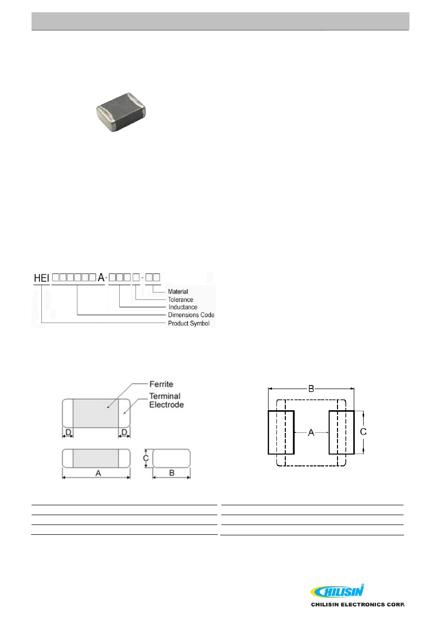
Product Identification
Shape and Dimensions
Recommended Pattern
Dimensions in mm
TYPE A B C D
201210A 2.0±0.2
1.25±0.2
1.0Max
0.5±0.3
201610A 2.0±0.2
1.60±0.2
1.0Max
0.5±0.3
Dimensions in mm
TYPE A
B
C
201210A 0.8~1.2 2.3~2.9 1.0~1.4
201610A 0.9
2.0
1.6