background image

Flame Retardant

Silicone Coating

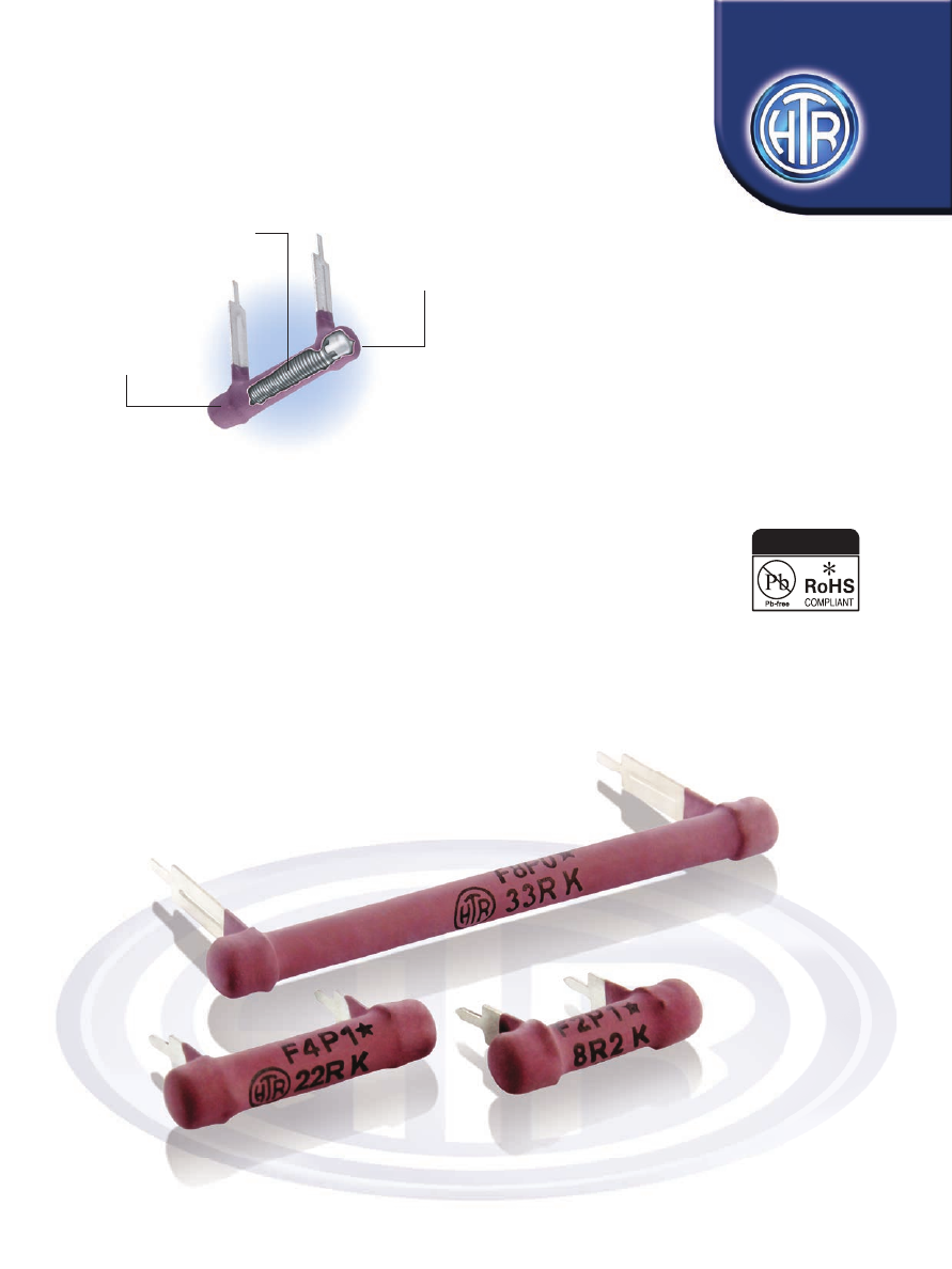
Alloy Resistance Wire, Wound

On Fibre Glass Core/

Ceramic Core

Mechanically Crimped,

Tin Plated,

PCB Type Termination

• Flame retardant coating compatible 


with UL standards

• Choice of terminals which are suitable 


for wave soldering

• 2.5W to 8W

• R10 to 56K

WIRE WOUND RESISTORS 

SILICONE COATED TYPE

HFP

SERIES

FIBRE GLASS SUBSTRATE

Silicone Coated

Wire Wound Resistors

Plug in Style

e : info@htr-india.com

www.htr-india.com

Rev Date : 22/05/2019

AEC-Q200 Qualifi ed

HTR-India-Products-Wire-Wound-Resistors-Silicone-Coated-Resistors-HFP-English-html.html
background image

PHYSICAL CONFIGURATION

PHYSICAL CONFIGURATION

HTR

TYPE

POWER

RATING

at 70°C

L

+2/-1

DIMENSIONS (mm)

RESISTANCE RANGE

TYPICAL

WEIGHT PER PC ‘1’

TERMINAL

(gms)

F-2P 

2.5W 

18.2 

5.0 

10.2 

R10 

10K 

1.38 

1.05

F-4P 

4W 

23.3 

5.0 

15.2 

R10 

15K 

1.70 

1.25

F-5P 

5W 

33.4 

5.0 

25.4 

R10 

27K 

2.10 

1.90

F-7P 

6.5W 

43.5 

5.0 

35.4 

R10 

39K 

2.80 

2.50

F-8P 

8W 

53.7 

5.0 

45.7 

R10 

56K 

3.10 

2.91

TYPICAL

WEIGHT PER PC ‘0’

TERMINAL

(gms)

 min                 max

D

±1

P

±1

*

CHOICE OF TERMINALS

•  If the longer stand-off terminal is required, suffix the type with ‘0’. For e.g. F-2 P-0 to F-8 P-0.

•  If the shorter stand-off terminal is required, suffix the type with ‘1’. For e.g. F-2 P-1 to F-8 P-1.

•  The resistance range given is applicable to the standard HFP series resistors. Pulse type resistors available. 

  Please consult factory and note (2) in ordering information.

    For resistance values <1R0, +0.8mm allowed.

*

1

0

WIRE WOUND 

RESISTORS

SILICONE 

COATED TYPE

HFP

C

CA

CZ

e : info@htr-india.com

www.htr-india.com

Rev Date : 22/05/2019

HTR-India-Products-Wire-Wound-Resistors-Silicone-Coated-Resistors-HFP-English-html.html
background image

TYPE

POWER

RATING

at

70°C

L

+2/-1

DIMENSIONS (mm)

RESISTANCE RANGE

TYPICAL WEIGHT PER PC (gms)

F-4P 

4W 

23.3 

5.0 

15.2 

R10 

15K 

1.8 

2.2 

1.8

F-5P 

5W 

33.4 

5.0 

25.4 

R10 

27K 

2.2 

2.4 

2.2

F-7P 

6.5W 

43.5 

5.0 

35.4 

R10 

39K 

2.9 

3.0 

2.8

F-8P 

8W 

53.7 

5.0 

45.7 

R10 

56K 

3.15 

3.2 

3.15

min         max

D

±1

P

±1.0

‘C’

terminal

‘CA’

terminal

‘CZ’

terminal

* For resistance values <1R0, +0.8mm allowed

• If the “C” type stand-off terminal is required, suffix the type with “C”. e.g. 

  F-4P-C to F-8P-C

• If the “CA” type stand-off terminal is required, suffix the type with “CA”. e.g. 

  F-4P-CA to F-8P-CA

• If the “CZ” type stand-off terminal is required, suffix the type with “CZ”. e.g. 

  F-4P-CZ to F-8P-CZ

CHOICE OF TERMINALS

*

WIRE WOUND 

RESISTORS

SILICONE 

COATED TYPE

HFP

ELECTRICAL AND ENVIRONMENTAL CHARACTERISTICS / DATA

Power Rating (Rated Ambient Temperature) 

Full Power dissipation at 70°C and linearly derated   


to zero at 350°C  (Refer Derating curve above) 

Resistance Tolerances Available 

±10% (K); ±5% (J) 

Temperature Range  

-55°C to +350°C with suitable derating as per derating curve 

Voltage Rating / Limiting Voltage / Max Working Voltage 

V=    PxR 

Maximum Overload Voltage 

Varies depending on resistance value, duration of overload   


and type of pulse waveform (contact factory for details) 

Voltage Proof / Dielectric Withstanding Voltage. 

R ± [1% + R05] - No flashover, mechanical   

(based on limiting voltage x 2 for 60 secs) 

damage, arcing or insulation breakdown 

Short Time Overload (5 x Rated Power for 5 secs) 

R ± [2% + R05]  

Temperature Co-efficient of Resistance 

± 60 to ±450 ppm/°C (Depending on resistance value) 

Temperature Cycling (Room Temperature 


   -55°C


R ± [2% + R05] 

Room Temperature         200°C 

Room Temperature for 5 cycles) 
Damp Heat (Steady State)  

R ± [2% + R05] - Average

(40°C at 93% R.H for 1000 hours - no load applied) 
Endurance - Load life 

R ± [3% + R05] - Average 

(70°C with limiting voltage - 1.5 hours on / 0.5 hours

off for 1000 hours) 
Solvent Resistance [IPA for 60 secs ± 10 secs] 

No effect on coating / marking 

PARAMETER/PERFORMANCE TEST & TEST METHOD 

PERFORMANCE REQUIREMENTS

Terminal Tensile Strength 

40 Newtons

Resistance to Soldering Heat  

R ± [0.2% + R05] - Typical 

(260°C - 270°C for 10 secs)
Solderability (As per IEC - 60068 - 2 - 20Ta) 

Must meet the requirements laid down 

Marking 

As per IEC Pub. 60062

PARAMETER/PERFORMANCE TEST & TEST METHOD 

PERFORMANCE REQUIREMENTS

MECHANICAL SPECIFICATIONS

TEMPERATURE RISE

1. Body Temperature Measuring Point

2. Solder Joint Temperature Measuring Point

e : info@htr-india.com

www.htr-india.com

Rev Date : 22/05/2019

HTR-India-Products-Wire-Wound-Resistors-Silicone-Coated-Resistors-HFP-English-html.html
background image

  TYPE

Temperature At Full Power Dissipation

F2P 

230

0

180

0

50

0

70

0

C

F4P 

285

0

235

0

53

0

98

0

55

0

52

0

49

0

F5P 

285

0

240

0

50

0

85

0

57

0

57

0

58

0

C

F7P 

292

0

260

0

45

0

85

0

62

0

55

0

55

0

F8P 

290

0

246

0

55

0

80

0

57

0

55

0

55

0

C

TYPICAL APPLICATIONS


The HFP series was evolved in order to provide a low cost but reliable alternative to those OEM’s who have automated assembly facilities 

including wave soldering. Due to their design, these resistors have merely to be plugged into the PCB and wave soldered.

ORDERING INFORMATION

1. For RoHS version - F8P *

2. For Pulse type - F8P I

‘C’ Type

Terminal

‘CA’ Type

Terminal

‘CZ’ Type

Terminal

‘1’ Type

Terminal

‘O’ Type

Terminal

Measuring Point 1

Measuring Point 2

High 

Resistance Range

Low 

Resistance Range

Note: In this series, there is a choice of  terminal stand-off heights available; please refer “PHYSICAL CONFIGURATION” for selection.

WIRE WOUND 

RESISTORS

SILICONE 

COATED TYPE

HFP

  Series 

Type 

Packing 

Resistance Value 

Tolerance 

Type of Termination


HFP 

F8P / F8P* 

Bulk F8P / F8P* 

100R 

0 / 1 / C / CA / CZ

e : info@htr-india.com

www.htr-india.com

Rev Date : 22/05/2019