background image

Alloy Resistance 

Wire Wound 

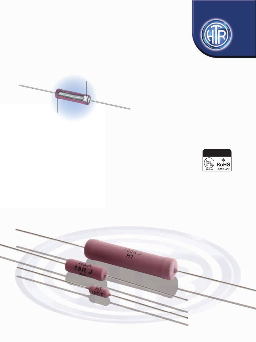
To Specifi c Parameters 

On High 

Thermal Conductivity 

Ceramic Core

All Welded Cap 

And Lead Assembly

Flame Retardant

Thermocoat

WIRE WOUND RESISTORS

SILICONE COATED TYPE

HIA

SERIES

PRECISION POWER

Silicone / Wire Wound Resistors

Industrial / Professional Applications

• Flame retardant coating compatible 

with UL standards

• 0.5W to 25W

• Tolerances as close as 0.25% possible

• R01 to 150K

• TCR as low as +20ppm/°C available depending


on application and resistance value

• Special types available for pulse 


applications-IEC 61000-4-5

e : info@htr-india.com

www.htr-india.com

Rev Date : 23/09/2022

AEC-Q200 Qualifi ed

HTR-India-Products-Wire-Wound-Resistors-Silicone-Coated-Resistors-HIA-English-html.html
background image

H0.5 
D0.5  
H1  

1W 

9.50 

4.5 

38 

0.8 

30 

R01 

5K0 

0.7

H2  

2W 

11.50 

4.5 

38 

0.8 

35 

R01 

6K2 

0.75

D2   

2W (70°C) 

14.50 

6.0 

38 

0.8 

35 

R01 

14K 

1.2

H3A  

3W 

11.50 

5.5 

38 

0.8 

35 

R01 

10K 

1.1

H3  

3W 

15.50 

6.0 

38 

0.8 

35 

R01 

15K 

1.4

H4  

4W 

15.50 

6.0 

38 

0.8 

35 

R01 

15K 

1.4

H5A  

5W 

19.25 

6.5 

38 

0.8 

40 

R01 

24K 

2.0

D5   

5W (70°C) 

22.50 

7.5 

38 

0.8 

45 

R01 

33K 

2.9

H5  

5W 

24.50 

8.7 

38 

0.8 

45 

R01 

47K 

4.0

H7A  

7W 

31.75 

9.5 

38 

0.8 

55 

R01 

68K 

5.2

H7  

7W 

38.50 

8.7 

38 

0.8 

60 

R01 

70K 

5.2

H10A  10W  43.50 10.0  38  0.8  65  R05  100K  7.2
H10  

10W 

53.50 

9.0 

38 

0.8 

75 

R10 

100K 

5.5

H15  

15W 

43.50 

10.0 

38 

1.0 

65 

R05 

100K 

8.2

H20    

20W 

67.00 

10.0 

38 

1.0 

90 

R10 

120K 

11.2

H25    

25W 

73.0 

10.0 

38 

1.0 

95 

1R0 

150K 

12.8

HTR

TYPE

POWER

RATING

at 40°C

L

(max)

*

D

(max)

DIMENSIONS (mm)

RESISTANCE RANGE

TYPICAL

WEIGHT 

PER PC

(gms)

min

max

d

±0.05

l

±1.5

LM

±1

PHYSICAL CONFIGURATION

(Ambient)

WIRE WOUND 

RESISTORS

SILICONE/

COATED TYPE

HIA

e : info@htr-india.com

www.htr-india.com

Rev Date : 23/09/2022

Dimension Applied for 

Bulk Specification 

Packing

Table 1.1 :


0.5W 

6.75 

4.5 

38 

0.8 

30 

R01 

2K0 

0.6

NON INDUCTIVE RESISTORS

Low inductance Aryton - Perry winding type resistors are available in this series. For non-inductive types reduce maximum resistance 

values shown to 50% and the continuous working voltage to 70% (please refer to note (2) of ordering information for placing orders).

PRE-FORMED LEADS

The resistor terminations can be bent and cut as per requirements for quick PCB mounting. Please send detailed drawings of specific 

type of preforming required. Depending on application the resistors leads may be tin plated Copper Weld ® instead of tin plated copper.

TAPING

Types H-0.5, D-0.5, H-1, H-2, D-2, H-3, H-3A, H-4, H-5A, H-5, D-5, H-7A, H-7, H-10A, H-10 and H-15 can be supplied in taped form.

Please refer to tape/ ammo pack specifications. Tape / Reel on request. Type H-5, D-5, H-7A, H-7, H-10A, H-10 and H-15 in taped will be 
supplied with tin plated copper clad steel (copper weld ®) terminations.

*  For non-inductive types and for resistance values <1R0, +0.8mm allowed.
 

Coating overflow on each lead not to exceed half of ‘D’.


For resistance values less than R10 and tolerance less than ±2%, please measure resistance over centered length LM.

•  Special Resistance values available on request.

HTR-India-Products-Wire-Wound-Resistors-Silicone-Coated-Resistors-HIA-English-html.html
background image

H0.5  

0.5W 

10 

52 

64 

100 

R01 

2K0 

0.6

D0.5  
H1  

1W 

10 

52 

64 

100 

R01 

5K0 

0.7

H2  

2W 

10 

52 

64 

100 

R01 

6K2 

0.75

D2   

2W (70°C) 

10 

63 

75 

100 

R01 

14K 

1.2

H3A  

3W 

10 

63 

75 

100 

R01 

10K 

1.1

H3  

3W 

10 

63 

75 

100 

R01 

15K 

1.4

H4  

4W 

10 

63 

75 

100 

R01 

15K 

1.4

H5A  

5W 

10 

74 

86 

100 

R01 

24K 

2.0

D5   

5W (70°C) 

10 

74 

86 

100 

R01 

33K 

2.9

H5  

5W 

10 

74 

86 

100 

R01 

47K 

4.0

H7A  

7W 

15 

74 

86 

150 

R01 

68K 

5.2

H7  

7W 

10 

79 

91 

100 

R01 

70K 

5.2

H10A  10W  6  15  79  91 150 R05  100K 7.2
H10 

  10W  6  15  90 102 150 R10  100K 5.5

H15  

15W 

15 

79 

91 

150 

R05 

100K 

8.2

HTR

TYPE

POWER

RATING

at 40°C

a

±1

s

±0.5

DIMENSIONS (mm)

RESISTANCE RANGE

TYPICAL

WEIGHT 

PER PC

(gms)

min

max

c

±2

b

±2

10x

S±2

(Ambient)

WIRE WOUND 

RESISTORS

SILICONE/

COATED TYPE

HIA

e : info@htr-india.com

www.htr-india.com

Rev Date : 23/09/2022

Note: Dimensions are applicable for Tape & Ammo / Tape & Reel 

Table 1.2 :

Where

a’ stands for width of the tape
b’ stands for inner distance between two tapes
c’ stands for outer distance between two tapes
e’ stands for the inner distance of the reel
f’ stands for the total width of the reel
S’ stands for the pitch between resistors

Note

The maximum difference between D1 & D2 is 1.40 mm
All dimensions stated below are in mm
Dimensions ‘e’ & ‘f’ are given as approximate guidelines only

30

3.0

f

e

a

b

c

s

D2

D1

330

±5

HTR-India-Products-Wire-Wound-Resistors-Silicone-Coated-Resistors-HIA-English-html.html
background image

HTR

TYPE

BULK PACKING

(For Dimension Refer to Table 1.1)

Number of Pieces

TAPE & AMMO PACKING

(For Dimension Refer to Table 1.2)

Number of Pieces

TAPE & REEL PACKING

(For Dimension Refer to Table 1.2)

Number of Pieces

PACKING CONFIGURATION

H0.5  

500 

1000 2000

D0.5  
H1  

500 

1000 2000

H2  

500 

1000 2000

D2  

400 

600 1250 

H3A  

500 

750 1250

H3  

400 

600 1250

H4  

400 

600 1250

H5A  

600 

600 1000 

D5  

400 

300 750

H5  

500 

300 750

H7A  

125 

175 450

H7  

125 

300 800

H10A 100 

175 450

H10  

120 

175 450

H15  

100 

175 450

H20    

100 

NA NA

H25    

100 

NA 

NA

Rev Date : 23/09/2022

ELECTRICAL CHARACTERISTICS/ DATA

Power Rating  

Full power dissipation at upto 40°C and linearly derated down 

(Rated Ambient Temperature) 

to zero dissipation at 275°C. [see Derating Curve above] 

Resistance Tolerances Available  

±10% [K]; ±5% [J]; ±3% [H]; ±2% [G]; ±1% [F];   

(Test method no. 303 of MIL 202F) 

±0.5% [D], ±0.25% [C]

Voltage Rating / Limiting Voltage / Max. Working Voltage 

V =    PxR 

Voltage Proof / Dielectric Withstanding Voltage Max. 

R ± (1% + R05) - No flashover, mechanical  

(based on limiting voltage x 2 or 500V whichever 

damage, arcing or insulation breakdown

is applicable) (Test Method no. 301 of  MIL 202F) 

Insulation Resistance (Test Method no. 302 of  MIL 202F) 

>1000 M (Dry) > 100M (Wet)

Short Time Overload Max. 

R ± (2% + R05) 

(Test Method - 5 secs at 5 times rated power for 3 watts 

and smaller; 5 secs at 10 times rated power for 4 watts and larger) 

Resistor Temperature Rise as a Function  

As temperature rise varies between different power ratings and 

of Applied Power 

ratings and also between different resistance values, if this parameter


is required in detail, please provide power rating (W) and resistance  


(R) required and factory will provide a suitable graph.

PARAMETER/PERFORMANCE TEST & TEST METHOD 

PERFORMANCE REQUIREMENTS

WIRE WOUND 

RESISTORS

SILICONE/

COATED TYPE

HIA

www.htr-india.com

PULSE CAPABILITY

•  Resistors for use under pulse conditions as per IEC - 61000 - 4 - 5 available. For further information please refer to “Pulse / Surge Capability 

of resistors”.

•  In-case a tailor made pulse resistor is required, please refer to “Questionnaire of data required” and provide   data accordingly.

•  Once power rating and resistance value are established by the design engineer, HTR can provide vital data in the form of charts/graphs 

for two important characteristics of the pulse version of these resistors - 1.Pulse on a regular basis ; Max allowable peak pulse power 

(W) as a function of pulse duration (T). 2.Pulse capability ; Energy (J) as 

  a function of R (Ω). 

It is essential that this data must be validated in actual trials and HTR will be pleased to provide the necessary samples for validation 

and homologation.

HTR-India-Products-Wire-Wound-Resistors-Silicone-Coated-Resistors-HIA-English-html.html
background image

WIRE WOUND 

RESISTORS

SILICONE/

COATED TYPE

HIA

ENVIRONMENTAL SPECIFICATIONS

Temperature Co-efficient of Resistance  

± 120ppm / °C (< R10); ± 80ppm / °C (<1R0);

(Test Method 304 of MIL 202F) 

± 60ppm /°C (<100R); ± 90ppm / °C or


± 30ppm /°C (>100R) depending on wire selected.

Temperature Cycling

Test Method as per JIS-C-5202 Para 7.4  

ΔR ± [2% + R05] - Typical

[Room Temperature ---> -55°C --->Room Temperature

---> +155°C ---> Room Temperature for 5 cycles] 
Damp Heat (Steady State)

(Test Method No. 103B of MIL 202F and test condition ‘D’) 

Max. Δ R ± (3% + R05) - No mechanical damage

Thermal Shock

(Test Method No. 107D of MIL 202F & Test Condition ‘B’) 

Max Δ R ±(3% + R05) - No physical Deterioration 

Load Life (Test Method no. 108A of MIL 202F)

(1000 hours intermittent @ 40°C) 

Max. ΔR ± (3.5% + R05)

PARAMETER/PERFORMANCE TEST & TEST METHOD 

PERFORMANCE REQUIREMENTS

e : info@htr-india.com

www.htr-india.com

Rev Date : 23/09/2022

MECHANICAL SPECIFICATIONS

PARAMETER/PERFORMANCE TEST & TEST METHOD 

PERFORMANCE REQUIREMENTS

Mechanical Shock

(Test Method No. 213B of MIL 202F) 

Test condition & requirement to be mutually decided.

Pull Test / Robustness of Termination

[Force supplied from 2 to 4.5Kgs depending on size] 

No mechanical damage

Vibration

(Test Method No. 201A of MIL 202F) 

Max ΔR ±(3% + R05) - No physical damage 

Solderability 

[Test method no.208F of MIL 202F] 

ΔR < ± [1% + R05] - Continuous and satisfactory

Resistance to Soldering Heat

(Test Method 210A of MIL 202 F & Test condition C) 

Max ΔR ±(2% + R05)

Resistance to Solvents 

Marking must remain Legible.

The usage of HIA series resistors will expand circuit design limits significantly because they have precision resistor characteristics with low 

TC and are able to carry load at high ambient temperatures.

HIA series can effectively be used in all industrial, electrical, electronic and telecommunication equipment where large power dissipation is 

required (e.g. when used as a voltage divider or bleeder resistor in DC power supplies or for series dropping). They are generally satisfactory 

for use at frequencies upto 50KHz.

HIA series when wound by the Aryton-Perry method can be used effectively for high frequency applications where fast rise time and 

minimum shift AC characteristics are necessary.
Note : Type H5, H7, H7A, H10, H10A can be supplied with lead diameter of 1.0mm. Please specify to avoid confusion.

TYPICAL APPLICATIONS

1.  For RoHS version - H-2*

2.  For Non Inductive type - N H2

3.  For Pulse type - H2 I

4.  For Tape and Ammo packing - H2 T

5.  For Tape and Reel - H2 TR

Item code will differ from ordering  information.


Series 

Type 

Packing 

Resistance Value 

Tolerance 


HIA 

H2 / H2* 

Bulk H2 / H2* 

100R 

J


Tape & Ammo H2*T / H2T


Tape & Reel H2*TR / H2TR 

ORDERING INFORMATION