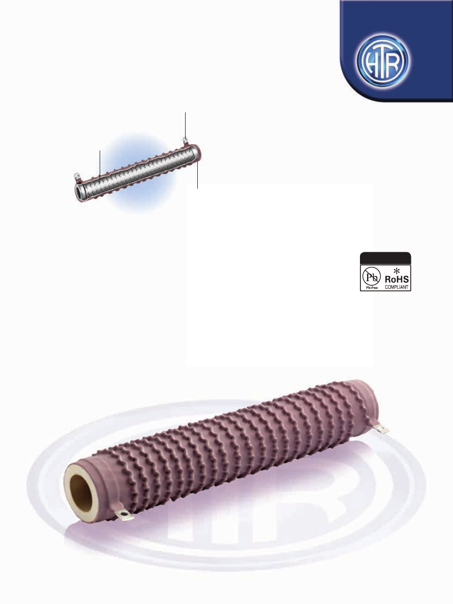
background image

Stainless steel / 

Nickel - plated 

Terminations

Flame Retardant

Silicone Coating

Alloy Resistance Strips, 

Corrugated and 

Wound Edgewise

On Ceramic Substrate

• Type ‘A’ compatible for using


with Amp type connectors.

• Flame retardant coating compatible 

with UL standards.

• 40W to 1000W

• R05 to 30R

WIRE WOUND RESISTORS

SILICONE COATED TYPE

RSR

SERIES

EDGE WOUND

Silicone Coated

Power Resistors Heavy Duty 

Industrial Applications

e : info@htr-india.com

www.htr-india.com

Rev Date : 25/09/2022

AEC-Q200 Qualifi ed

HTR-India-Products-Wire-Wound-Resistors-Silicone-Coated-Resistors-RSR-html.html
background image

TYPE

POWER

RATING

at 70°C

L

±3

*

D

±2

d

±1

W

±0.35

H

+2/-0

DIMENSIONS (mm)

RESISTANCE 

RANGE 

    min 

max

RR40A  40W  75.0 30.0 14.3  4.75 1.4  6.35  102/303 R05  1R9  63.0

RR40B  40W  75.0 30.0 14.3  5.0  3.0  8.5  102/303 R05  1R9  64.5

RR50A  50W  100.0 30.0  14.3  4.75  1.4  6.35  102/303  R07  2R0  80.0

RR50B  50W  100.0 30.0  14.3  5.0  3.0  8.5 

102/303  R07  2R0  82.0

RR60A  60W  115.0 30.0  14.3  6.35 1.65  8.5 

102/303  R075  2R2  95.0

RR60B  60W  115.0 30.0  14.3  8.0  4.3  11.0  102/303 R075  2R2  97.0

RR80A  80W  130.0 30.0  14.3  6.35 1.65  8.5 

102/303  R09  3R0  102.0

RR80B  80W  130.0 30.0  14.3  8.0  4.3  11.0  102/303  R09  3R0  104.0

RR100A  100W  105.0 37.0  19.1  6.35 1.65  8.5 

103/303  R10  2R9  112.0

RR100B  100W  105.0 37.0  19.1  8.0  4.3  11.0  103/303  R10  2R9  115.0

RR120A  120W  115.0  37.0  19.1  6.35 1.65  8.5 

103/303  R10  4R0  123.0

RR120B  120W  115.0 37.0  19.1  8.0  4.3  11.0  103/303  R10  4R0  125.0

RR150A  150W  140.0 37.0  19.1  6.35 1.65  8.5 

103/303  R20  5R0  187.0

RR150B  150W  140.0 37.0  19.1  8.0  4.3  11.0  103/303  R20  5R0  190.0

RR200A 200W  200.0 37.0  19.1  6.35 1.65  8.5 

103/303  R20  7R0  242.0

RR200B 200W  200.0 37.0  19.1  8.0  4.3  11.0  103/303  R20  7R0  245.0

RR300A 300W  250.0 48.0  24.0  6.35 1.65  8.5 

104/304  R50  10R  573.0

RR300B  300W  250.0 48.0  24.0  8.0  4.3  11.0  104/304  R50  10R  575.0 

RR400A 400W  300.0 48.0  24.0  6.35 1.65  8.5 

104/304  R50  14R  740.0

RR400B 400W  300.0 48.0  24.0  8.0  4.3  11.0  104/304  R50  14R  744.0

RR500A 500W  300.0 58.0  27.0  6.35 1.65  8.5 

104/304  1R0  18R  1180.0

RR500B  500W  300.0 58.0  27.0  8.0  4.3  11.0  104/304  1R0  18R  1190.0

RR600A 600W  330.0 58.0  27.0  6.35 1.65  8.5 

104/304  1R0  20R  1300.0

RR600B 600W  330.0 58.0  27.0  8.0  4.3  11.0  104/304  1R0  20R  1310.0

RR1000A 1000W  380.0  78.0  48.5  6.35  1.65  9.5 

105/305  1R0  30R 

1840

RR1000B 

1000W 

380.0  

78.0 

48.5 

8.0 

4.3 

12.0 

105/305 

1R0 

30R 

1860

INDICATIVE

WEIGHT 

PER PC

(gms)

MOUNTING

HARDWARE

AVAILABLE

PHYSICAL CONFIGURATION

*

  D-Dimensions given are indicative and could exceed tolerances given depending on resistance value being wound.

*

  Resistor types suffixed with ‘A’ are compatible with Amp 187 connectors from 40 watt to 50 watt size and are compatible with 

Amp 250 connectors from 60 watt to 600 watt size. Resistor types suffixed with ‘B’ have large center holes in the lugs-refer 

Øld, to facilitate attaching cables to them by using nut & bolt or soldering after threading the wires through them.

∅ 

ld

±0.3

WIRE WOUND 

RESISTORS

SILICONE

COATED

TYPE

RSR

MOUNTING SPECIFICATIONS

e : info@htr-india.com

www.htr-india.com

Rev Date : 25/09/2022

HTR-India-Products-Wire-Wound-Resistors-Silicone-Coated-Resistors-RSR-html.html
background image

ELECTRICAL AND ENVIRONMENTAL CHARACTERISTICS / DATA

Full Power dissipation at 70°C and linearly derated to zero at 350°C 
(Refer Derating curve above).
±10% (K) ± 5(J) on request. 
-55°C to + 350°C with suitable derating as per derating curve above.
V =   PxR
< R10 ± 120 ppm /°C ; < 1R0 ± 80 ppm /°C
> 1R0 ± 60 ppm /°C

R ± [2% + R05]

PARAMETER/PERFORMANCE TEST & TEST METHOD 

PERFORMANCE REQUIREMENTS

Power Rating (Rated Ambient Temperature)

Resistance Tolerances Available
Temperature Range
Voltage Rating / Limiting Voltage / Max working Voltage
Temperature Co-efficient

Short Time Overload (10 x Rated Power for 5 secs)

BRACKET

TYPE

 Y

±

1.0mm

Z

±

2mm

H

±

2mm

MOUNTING

SLOT

±

0.5mm

C

±

2mm

B

±

2mm

  102 

20.0 

25.0 

33.0 

5.5 x 11.0 

20.0 

46.0

  103 

32.0 

30.0 

37.0 

7.0 x 11.0 

22.0 

54.0

  104 

48.0 

32.0 

57.0 

7.0 x 11.0 

23.0 

82.0

  105 

72.0 

40.0 

65.0 

8.5 x 12.0 

30.0 

101.0

BRACKET

TYPE

X (APPROXIMATE)

(mm)

 303 

15.0

 304 

16.0

 305 

26.0

WIRE WOUND 

RESISTORS

SILICONE

COATED

TYPE

RSR

TYPICAL APPLICATIONS


In RSR series, a corrugated alloy tape is wound edgewise or flat onto a ceramic tube which is coated with a silicone cement which is 

compatible with UL standards.  

This ribbed construction puts both sides of the resistive element in contact with air thus creating a convention area four times greater 

than that obtained with normal wire wound resistors.  

These resistors are designed primarily to withstand heavy overload surges upto max 7 times their rated wattage for 10 to 15 seconds 

(max). This characteristic makes them most suitable for controlling motors requiring high dissipation, low resistance values and high 

current capacity.

ORDERING INFORMATION

1.  For RoHS version - RR200B *

2.  For Non inductive type - N RR200B

  Series 

  HTR Type 

Packing 

Resistance Value  

Tolerance 

Type of Mounting Hardware


RSR 

RR200B/RR200B* 

Bulk RR200B/RR200B* 

3R0 

103 / 303

e : info@htr-india.com

www.htr-india.com

Rev Date : 25/09/2022