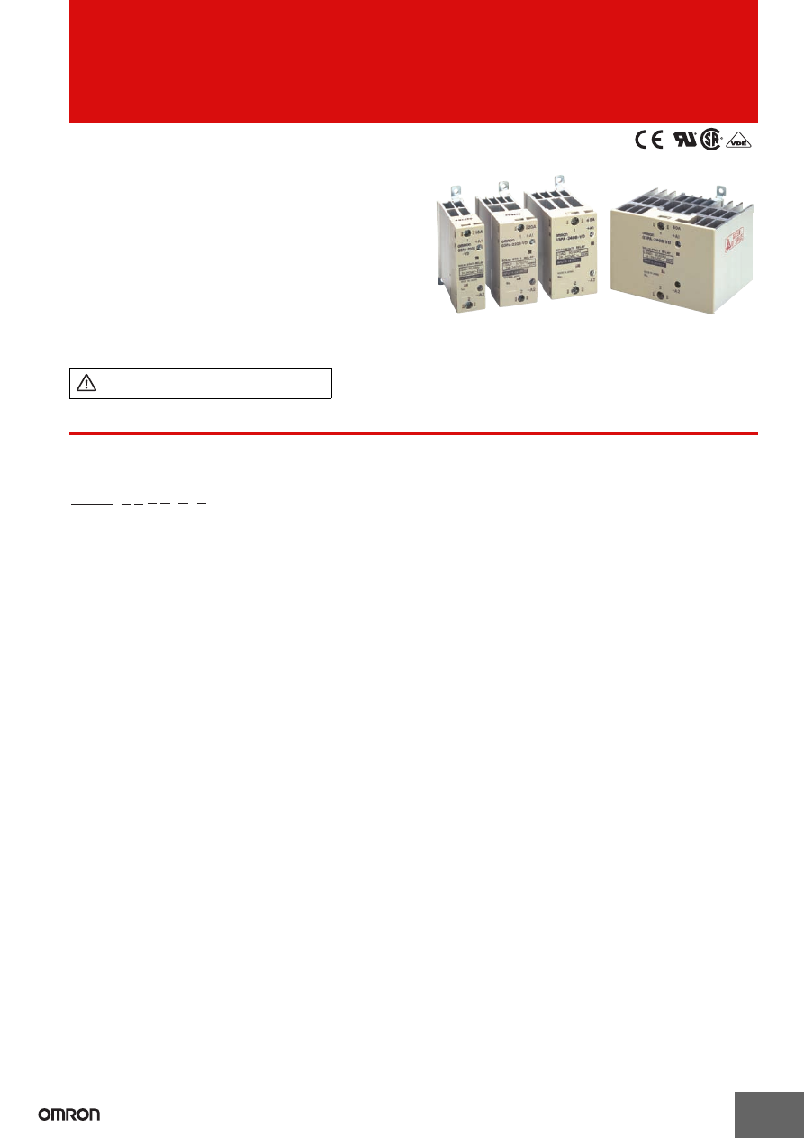
background image

1

CSM_G3PA_DS_E_3_3

Solid State Relays

G3PA

Extremely Thin Relays Integrated with Heat 

Sinks

• Downsizing achieved through optimum design of heat sink.
• Mounting possible via screws or via DIN track.
• Close mounting possible for linking terminals. (Except for 

G3PA-260B-VD and G3PA-450B-VD-2.)

• Applicable with 3-phase loads.
• Replaceable power element cartridges.
• Comply with VDE 0160 (finger protection), with a dielectric 

strength of 4,000 V between input and load.

• Certified by UL, CSA, and VDE (reinforced insulation).

 *

* Only UL and CSA certification applies to model numbers that end in 

-VD-X.

Refer to 

Safety Precautions for All Solid State 

Relays

.

*

* Not applicable to model 

numbers that end in -VD-X.

For the most recent information on models that have been certified for 
safety standards, refer to your OMRON website.

Note:

Manufacture of the following models will be discontinued at 

the end of March 2017: G3PA-210B-VD, G3PA-220B-VD, 

G32A-A10-VD, and G32A-A20VD.

Model Number Structure

Model Number Legend

1. Basic Model Name

G3PA:Solid State Relay

2. Rated Load Power Supply Voltage

2:

200 VAC

4:

400 VAC

3. Rated Load Current

10:

10 A

20:

20 A

30:

30 A

40:

40 A

50:

50 A

60:

60 A

4. Terminal Type

B:

Screw terminals

5. Zero Cross Function

Blank: Equipped with zero cross function
L:

Not equipped with zero cross function

6. Certification

VD:

Certified by UL, CSA, and VDE

7. Special Specifications

Blank: Standard models
2:

480-V models

X:

Non-compliant of EN standard (CE mark)

1

2 3 4 5

6

7

G3PA-

@@@@-@-@

Omron-G3PA-html.html
background image

G3PA

2

Ordering Information

List of Models

Note:

When ordering, specify the rated input voltage.

* Manufacture will be discontinued at the end of March 2017.

Replacement Parts

* Manufacture will be discontinued at the end of March 2017.

Other Units (Order Separately)

Units that Enable 2-line Switching of 3-phase Power

Note:

Refer to 

List of Certified Models 

for a list of products that comply with safety standards.

Model

Isolation

Zero cross function

Indicator

Rated output load

Rated input voltage

G3PA-210B-VD-X

Phototriac 

coupler

Yes

Yes

10 A at 24 to 240 VAC

5 to 24 VDC

G3PA-210B-VD *
G3PA-220B-VD-X

20 A at 24 to 240 VAC

G3PA-220B-VD *
G3PA-240B-VD

40 A at 24 to 240 VAC

G3PA-260B-VD

60 A at 24 to 240 VAC

G3PA-210BL-VD

No

10 A at 24 to 240 VAC

G3PA-220BL-VD

20 A at 24 to 240 VAC

G3PA-240BL-VD

40 A at 24 to 240 VAC

G3PA-260BL-VD

60 A at 24 to 240 VAC

G3PA-210B-VD

Yes

10 A at 24 to 240 VAC

24 VAC

G3PA-220B-VD

20 A at 24 to 240 VAC

G3PA-240B-VD

40 A at 24 to 240 VAC

G3PA-260B-VD

60 A at 24 to 240 VAC

G3PA-420B-VD

20 A at 180 to 400 VAC

12 to 24 VDC

G3PA-430B-VD

30 A at 180 to 400 VAC

G3PA-420B-VD-2

20 A at 200 to 480 VAC

G3PA-430B-VD-2

30 A at 200 to 480 VAC

G3PA-450B-VD-2

50 A at 200 to 480 VAC

Name

Carry current

Load voltage range

Model

Applicable SSR

VDE 

certification

Power Device 

Cartridge

10 A

19 to 264 VAC

G32A-A10-VD-X DC5-24

G3PA-210B-VD DC5-24

G3PA-210B-VD-X DC5-24

No

G32A-A10-VD DC5-24 *

G3PA-210B-VD DC5-24

Yes

G32A-A10L-VD DC5-24

G3PA-210BL-VD DC5-24

G32A-A10-VD AC24

G3PA-210B-VD AC24

20 A

G32A-A20-VD-X DC5-24

G3PA-220B-VD DC5-24

G3PA-220B-VD-X DC5-24

No

G32A-A20-VD DC5-24 *

G3PA-220B-VD DC5-24

Yes

G32A-A20L-VD DC5-24

G3PA-220BL-VD DC5-24

G32A-A20-VD AC24

G3PA-220B-VD AC24

40 A

G32A-A40-VD DC5-24

G3PA-240B-VD DC5-24

G32A-A40L-VD DC5-24

G3PA-240BL-VD DC5-24

G32A-A40-VD AC24

G3PA-240B-VD AC24

60 A

G32A-A60-VD DC5-24

G3PA-260B-VD DC5-24

G32A-A60L-VD DC5-24

G3PA-260BL-VD DC5-24

G32A-A60-VD AC24

G3PA-260B-VD AC24

20 A

150 to 440 VAC

G32A-A420-VD DC12-24

G3PA-420B-VD DC12-24

30 A

G32A-A430-VD DC12-24

G3PA-430B-VD DC12-24

20 A

180 to 528 VAC

G32A-A420-VD-2 DC12-24

G3PA-420B-VD-2 DC12-24

30 A

G32A-A430-VD-2 DC12-24

G3PA-430B-VD-2 DC12-24

50 A

G32A-A450-VD-2 DC12-24

G3PA-450B-VD-2 DC12-24

Name

Current flow

Model

Applicable SSR

Short-circuit Unit

10 A

G32A-D20

G3PA-210B-VD-X, G3PA-210BL-VD

20 A

G3PA-220B-VD-X, G3PA-220BL-VD

G3PA-420B-VD, G3PA-420B-VD-2

30 A

G32A-D40

G3PA-430B-VD, G3PA-430B-VD-2

40 A

G3PA-240B-VD, G3PA-240BL-VD

Omron-G3PA-html.html
background image

G3PA

3

Specifications

Ratings (at an Ambient Temperature of 25

°

C)

Input

Output

Refer to 

Engineering Data

 for further details.

Model

Rated voltage

Operating Voltage 

range

Input current 

impedance

Voltage level

Must operate voltage

Must release voltage

G3PA-210B-VD-X

5 to 24 VDC

4 to 30 VDC

7 mA max.

4 VDC max.

1 VDC min.

G3PA-220B-VD-X
G3PA-240B-VD
G3PA-260B-VD
G3PA-210BL-VD

5 to 24 VDC

4 to 30 VDC

20 mA max.

4 VDC max.

1 VDC min.

G3PA-220BL-VD
G3PA-240BL-VD
G3PA-260BL-VD
G3PA-210B-VD

24 VAC

19.2 to 26.4 VAC

1.4 k

Ω±

20%

19.2 VAC max.

4.8 VAC min.

G3PA-220B-VD
G3PA-240B-VD
G3PA-260B-VD
G3PA-420B-VD

12 to 24 VDC

9.6 to 30 VDC

7 mA max.

9.2 VDC max.

1 VDC min.

G3PA-430B-VD
G3PA-420B-VD-2
G3PA-430B-VD-2
G3PA-450B-VD-2

Model

Rated load voltage

Load voltage range

Load current

Inrush current

V

DRM

(reference value)

G3PA-210B(L)-VD(-X)

24 to 240 VAC (50/60 Hz) 19 to 264 VAC (50/60 Hz) 0.1 to 10 A at 40°C

150 A (60 Hz, 1 cycle) 600 V (V

DRM

)

G3PA-220B(L)-VD(-X)

0.1 to 20 A at 40°C

220 A (60 Hz, 1 cycle)

G3PA-240B(L)-VD

0.5 to 40 A at 40°C

440 A (60 Hz, 1 cycle)

G3PA-260B(L)-VD

0.5 to 60 A at 40°C

440 A (60 Hz, 1 cycle)

G3PA-420B-VD

180 to 400 VAC (50/60 Hz) 150 to 440 VAC (50/60 Hz) 0.5 to 20 A at 30°C

220 A (60 Hz, 1 cycle) 1,000 V (V

DRM

)

G3PA-430B-VD

0.5 to 30 A at 30°C

440 A (60 Hz, 1 cycle)

G3PA-420B-VD-2

200 to 480 VAC (50/60 Hz) 180 to 528 VAC (50/60 Hz) 0.5 to 20 A at 30°C

220 A (60 Hz, 1 cycle) 1,200 V (V

DRM

)

G3PA-430B-VD-2

0.5 to 30 A at 30°C

440 A (60 Hz, 1 cycle)

G3PA-450B-VD-2

0.5 to 50 A at 30°C

440 A (60 Hz, 1 cycle)

Omron-G3PA-html.html
background image

G3PA

4

Characteristics

Item

G3PA-

210B(L)-VD(-X)

G3PA-

220B(L)-VD(-X)

G3PA-

240B(L)-VD

G3PA-

260B(L)-VD

G3PA-

420B-VD

G3PA-

420B-VD-2

G3PA-

430B-VD

G3PA-

430B-VD-2

G3PA-

450B-VD-2

Operate 

time

1/2 of load power source cycle + 1 ms max. (DC Input, -B models)

1 1/2 of load power source cycle + 1 ms max. (AC Input)

1 ms max. (-BL models)

Release 

time

1/2 of load power source cycle + 1 ms max. (DC Input)

1 1/2 of load power source cycle + 1 ms max. (AC Input)

Output ON 

voltage drop

1.6 V (RMS) max.

1.8 V (RMS) max.

Leakage 

current

5 mA max. (at 100 VAC)

10 mA max. (at 200 VAC)

10 mA max. (at 100 VAC)

20 mA max. (at 200 VAC)

20 mA max.

(at 400 VAC)

20 mA max.

(at 480 VAC)

20 mA max.

(at 400 VAC)

20 mA max. (at 480 

VAC)

I

2

t

260 A

2

s

1,260 A

2

s

260 A

2

s

1,800 A

2

s

1,800 A

2

s

1,800 A

2

s

Insulation 

resistance

100 M

Ω

 min. (at 500 VDC)

Dielectric 

strength

4,000 VAC, 50/60 Hz for 1 min

Vibration 

resistance

Destruction: 10 to 55 to 10 Hz, 0.375–mm single amplitude (Mounted to DIN track)

Shock 

resistance

Destruction: 300 m/s

2

 (mounted to DIN track)

Ambient 

temperature

Operating: –30

°

C to 80

°

C (with no icing or condensation)

Storage:

–30

°

C to 100

°

C (with no icing or condensation)

Certified 

standards

UL508, CSA C22.2 (No.14, No.950), EN60950-1 File No. 

5915ÜG

UL508, 

CSA C22.2 

(No.14), 

EN60947-4-3

File No. 

6642ÜG

UL508, 

CSA C22.2 

(No.14), 

EN60947-4-3

File No. 

133127ÜG

UL508, 

CSA C22.2 

(No.14), 

EN60947-4-3

File No. 

6642ÜG

UL508, CSA C22.2 

(No.14), EN60947-4-3 

File No. 133127ÜG

EMC

Emission: EN55011 Group 1 Class A
Immunity: EN61000-6-2

Ambient 

humidity

Operating: 45% to 85%

Weight

Approx. 

260 g

Approx. 

340 g

Approx. 

460 g

Approx. 

900 g

Approx. 

290 g

Approx. 

290 g

Approx. 

410 g

Approx. 

410 g

Approx. 

900 g

Omron-G3PA-html.html
background image

G3PA

5

Operation

Replacement Parts

G32A-A Power Device Cartridge

The G32A-A Power Device Cartridge (a Triac Unit) can be replaced with a new one. When the temperature indicator has changed from pink to 

red, the triac circuitry may have malfunctioned possibly by an excessive flow of current, in which case, dismount the damaged cartridge for 

replacement.
The damaged cartridge can be replaced with a new one without disconnecting the wires from the G3PA.
Improve the heat radiation efficiency of the G3PA before replacing the cartridge.
The G32A-A Power Device Cartridge can withstand an excessive current for a short period of time, such as may be caused accidentally by the 

short circuitry of the load, in which case the temperature indicator will not turn red.
Be sure to turn OFF the power supply when replacing the Cartridge. Supplying power with the Cartridge removed may result in malfunction.
To remove or replace the Power Device Cartridge for the G3PA-210B(L)-VD(-X), G3PA-220B(L)-VD(-X), or G3PA-420B-VD(-2), use the special 

tool provided with it for extraction. (No special tool is required for other models.) 
The G3PA can be broadly divided into two series: Previous models and models with model numbers that end with "-VD." The Cartridge shown at 

the right cannot be mounted to models in the G3PA-

@@@

B-(-US) Series.

Appearance

Replacing Power Device Cartridges

When replacing Power Device Cartridges, use the specified model. Using a Power Device Cartridge other than the specified one will result in faulty 

operation and destruction of the elements.

G32A-A10(L)-VD(-X)

G32A-A420-VD(-2)

G32A-A430-VD(-2)

G32A-A450-VD-2

G32A-A20(L)-VD(-X) G32A-A40(L)-VD

G32A-A60(L)-VD

Omron-G3PA-html.html
background image

G3PA

6

Replacement Procedure

G32A-A10(L)-VD(-X)/G32A-A20(L)-VD(-X)/G32-A420-VD(-2)

To remove or replace the Power Device Cartridge, use the special tool provided with it for extraction. 

(Do not switch on the power without the Power Device Cartridge. For details, see the attached the instruction sheet with the product.)

Extraction

Follow the procedures below to dismount the Power Device 

Cartridge from the G3PA.

1. Switch off the power.
2.

Remove the terminal cover.

3.

Hook the indented part of the cartridge with the tool and pull up on 

the cartridge to remove it.

Mounting

Follow the procedures below to mount the Power Device Cartridge 

on the G3PA.

1.

Apply silicone grease (provided with the G32A-A) to the entire 

surface of the heat sink.

2.

Make sure that there is no dust or pieces of wire on the heat sink 

of the G32A-A or the G3PA.

3.

Insert the cartridge into the opening of the G3PA so that the 

letters on the cartridge and those on the G3PA are in the same 

direction and side A and side B are even.

4.

Attach the terminal cover.

5.

Switch on the power and check the G3PA to be sure it works 

properly.

G32A-A40(L)-VD/G32A-A60(L)-VD/G32A-A430-VD(-2)/G32A-A450-VD-2

The G32A Power Device Cartridge is mounted and secured with screws to the G3PA Unit. No special tool is required to remove the Cartridge.

Extraction

Follow the procedures below to dismount the G32A-A Power Device 

Cartridge from the G3PA.

1. Switch off the power.
2.

Remove the terminal cover.

3.

Loosen the two centered screws on the sides to dismount the 

cartridge. The screws are connected to terminals 1 and 2.

4.

Loosen the screws on both the corners.

5.

Hold the indented part of both the corners to dismount the 

cartridge.

Mounting

1.

Apply silicone grease to the entire surface of the heat sink.

2.

Make sure that there is no dust or pieces of wire on the heat sink 

of the G32A-A or the G3PA.

Remover

Hook here with 
Remover.

Apply silicone grease here.

Side A

Side B

Loosen

Loosen

Loosen

Loosen

Apply silicone grease here.

Omron-G3PA-html.html
background image

G3PA

7

3.

Insert the cartridge into the opening of the G3PA so that side A 

and side B are even.

4.

Tighten the screws on both the corners with a tightening torque of 

0.59 to 0.78 N·m.

5.

Tighten the screws on both the sides with a tightening torque of 

0.59 to 0.78 N·m.

6.

Attach the terminal cover.

7.

Switch on the power and check the G3PA to be sure it works 

properly.

Linking Terminal Connection

Connecting with linking terminal for G3PA-210B(L)-VD(-X), 

-220B(L)-VD(-X), -240B(L)-VD and G3PA-420B-VD(-2), G3PA-

430B-VD(-2).

Connecting with linking terminal for G32A.

Side B

Side A

SSR1

SSR2

SSR1

SSR2

1.   When SSRs are close 

mounted, loosen the 
M3.5 Sems screw and 
flip the linking terminal 
down.

2.   Insert the linking 

terminal securely 
into the center of 
the screw and 
tighten the screw.

*

SSR

G32A Unit

SSR

G32A Unit

* The cover will not fit if 

the terminal protrudes.

1.   When SSR are close 

mounted, loosen the 
M3.5 Sems screw on 
the G32A and flip the 
linking terminal down.

2.   Insert the linking terminal 

securely into the center 
of the screw and tighten 
the screw. Ensure that 
the linking terminal does 
not protrude.

Linking terminal

Linking terminal

Connect the terminal with power off.

G3PA-420B-VD

Refer to the instruction manual for 
the G32A-A Power Device Cartridge 
to replace the G3PA's triac part.

When the temperature indicator has turned from pink to red, the G32-A-A Power Device Cartridge 
may have malfunctioned, in which case the cartridge must be replaced with a new one.

Use the terminal cover to prevent accidents 
due to electric shock.

Linking 
terminal

Linking 
terminal

Omron-G3PA-html.html
background image

G3PA

8

Engineering Data

Load Current vs. Ambient Temperature

For close mounting of two or three SSRs, limit the load current to 90% or less.

For close mounting of two or three SSRs, limit the load current to 80% or less.

25

15

40

60

80

100

20

0

-20

-30

60

40

25

20

80

Panel

Ground

Ambient temperature (

°

C)

Ambient temperature (

°

C)

Ambient temperature (

°

C)

Load current (A)

Load current (A)

Load current (A)

Vertical Mounting

G3PA-240B(L)-VD

G3PA-260B(L)-VD

G3PA-220B(L)-VD(-X)

G3PA-210B(L)-VD(-X)

G3PA-210B(L)-VD(-X), 
G3PA-220B(L)-VD(-X)

Ambient temperature (

°

C)

Ambient temperature (

°

C)

Load current (A)

Load current (A)

G3PA-430B-VD, G3PA-430B-VD-2

G3PA-420B-VD, G3PA-420B-VD-2

G3PA-450B-VD-2

Ambient temperature (

°

C)

Load current (A)

Omron-G3PA-html.html
background image

G3PA

9

Input Voltage vs. Input Current

G3PA-2

@

0B-VD(-X)

Input current (mA)

Input voltage (V)

Input current (mA)

Input voltage (V)

G3PA-4

@0

-VD, G3PA-4

@

-VD-2

40

20

10

8

6

4

2

1

0.1

0.2

0.4

0.6

0.8

1

2

4

6

8

Input impedance

Input current

Ta = 25

°

C

40

20

10

8

6

4

2

1

0.1

0.2

0.4

2

4

6

8

10

1

0.6

0.8

Input impedance

Input
current

T = 25

°

C

Input impedance (k

Ω

)

Input impedance (k

Ω

)

40

60

80

100

20

0

20

30

60

40

42

20

3.5

11

28

15

11

14

18

20

10

5

5.5

10

7

Panel

Ground

Ambient temperature (

°

C)

Ambient temperature (

°

C)

Ambient temperature (

°

C)

Load current (A)

Load current (A)

Load current (A)

G3PA-240B(L)-VD

G3PA-260B(L)-VD

G3PA-220B(L)-VD(-X)

Horizontal Mounting

G3PA-210B(L)-VD(-X), 
G3PA-220B(L)-VD(-X)

G3PA-210B(L)-VD(-X)

Ambient temperature (

°

C)

Load current (A)

G3PA-430B-VD

G3PA-420B-VD

G3PA-450B-VD-2

Ambient temperature (

°

C)

Load current (A)

G3PA-420B-VD, G3PA-430B-VD 
G3PA-420B -VD-2, G3PA-430B-VD-2

Omron-G3PA-html.html
background image

G3PA

10

40

30

24

20

10

30

10

30

80

30

20

16

10

30

10

30

80

100

40

60

80

100

20

0

-20

-30

64

40

48

20

18

4.5

36

15

13

20

30

5

7

40

45

30

20

10

14

9

27

Ambient temperature (

°

C)

G3PA-430B-VD, G3PA-430B-VD-2

Load current (A)

Ambient temperature (

°

C)

Load current (A)

G3PA-420B-VD, G3PA-420B-VD-2

Ambient temperature (

°

C)

Ambient temperature (

°

C)

Ambient temperature (

°

C)

Load current (A)

Load current (A)

Load current (A)

G3PA-240B(L)-VD

G3PA-260B(L)-VD

G3PA-220B(L)-VD(-X)

G3PA-210B(L)-VD(-X)

DIN track

Panel

Ground

Close Mounting (Up to Three)

G3PA-210B(L)-VD(-X), 
G3PA-220B(L)-VD(-X)

G3PA-450B-VD-2

Ambient temperature (

°

C)

Load current (A)

Omron-G3PA-html.html
background image

G3PA

11

One Cycle Surge Current: Non-repetitive

Note:

Keep the inrush current to half the rated value if it occurs repetitively.

G3PA-210B(L)-VD(-X)

G3PA-220B(L)-VD(-X), 
G3PA-420B-VD, G3PA-420B-VD-2

G3PA-240B(L)-VD/260B(L)-VD, 
G3PA-430B-VD, G3PA-430B-VD-2, 
G3PA-450B-VD-2

Inr

ush current (A.

 P

eak)

Energized time (ms)

Inr

ush current (A.

 P

eak)

Energized time (ms)

Inr

ush current (A.

 P

eak)

Energized time (ms)

Omron-G3PA-html.html
background image

G3PA

12

Dimensions

Note:

All units are in millimeters unless otherwise indicated.

G3PA-210B(L)-VD(-X)

Two, 4.5 dia. or M4 holes

4.6 dia.

Two, M4

100 max.

Mounting 
Holes

Without Terminal 
Cover

With Terminal 
Cover

Linking terminal B1

Linking 
terminal B2

Two, 
M3.5

4.6 x 5.6 elliptical 
hole

Terminal 
Arrangement/ 
Internal Connections

T

rigger circuit

Input circuit

G3PA-220B(L)-VD(-X)

Two, 4.5 dia. or M4 holes

4.6 dia.

Two, M4

100 max.

Mounting 
Holes

Without Terminal 
Cover

With Terminal 
Cover

Linking terminal B1

Two, 
M3.5

Linking terminal B2

4.6 x 5.6 elliptical 
hole

Terminal 
Arrangement/ 
Internal Connections

T

rigger circuit

Input circuit

G3PA-240B(L)-VD

4.6 dia.

Two, M5

100 max.

Two, 4.5 dia. or M4 holes

Mounting 
Holes

Without Terminal 
Cover

With Terminal 
Cover

Linking 
terminal B1

Two, 
M3.5

Linking 
terminal B2

4.6 x 5.6 elliptical 
hole

Terminal 
Arrangement/ 
Internal Connections

T

rigger circuit

Input circuit

Omron-G3PA-html.html
background image

G3PA

13

Two, 4.5 dia. 
or M4 holes

4.6 dia.

Two, M5

100 max.

Two, M3.5

110 max.

Mounting Holes

With Terminal 
Cover

Without Terminal 
Cover

G3PA-260B(L)-VD 
G3PA-450B-VD-2

4.6 x 5.6 
elliptical hole

Terminal Arrangement/ 
Internal Connections

T

rigger circuit

Input circuit

T

rigger circuit

Input circuit

G3PA-260B
-VD

G3PA-450B
-VD-2

1

+

A1

A2

2

1

+

A1

A2

2

4.5

7.6

2.2

8.8

13.2

8.6

90

±

0.2

25

±

0.2

90

±

0.3

90

91

67

38

80

Two, M4

Two, M3.5

4.6 dia.

37 max.

4.5 x 5.6 elliptic hole

100 max.

G3PA-420B-VD, G3PA-420B-VD-2

Mounting Holes

Terminal Arrangement/ 
Internal Connections

T

rigger circuit

Input circuit

100 
max.

Linking 
terminal 

B2

Linking 
terminal 
+B1

Two, 4.5 dia. or M4

Without Terminal 
Cover

With Terminal 
Cover

89

91

4.5

13

18

13

7.6

35

±

0.2

35

±

0.3

90

±

0.3

67

38

80

90

±

0.2

4.6 dia.

100 max.

47 max.

4.6 x 5.6 
elliptic hole

G3PA-430B-VD, G3PA-430B-VD-2

Mounting Holes

Two, 4.5 dia. or M4

Two, M5

Terminal Arrangement/ 
Internal Connections

T

rigger circuit

Input circuit

Linking 
terminal 
+B1

Linking 
terminal 

B2

100 
max.

Without Terminal 
Cover

With Terminal 
Cover

Omron-G3PA-html.html
background image

G3PA

14

Safety Precautions

Precautions for Correct Use

Please observe the following precautions to prevent failure to 
operate, malfunction, or undesirable effect on product performance. 

Load Connection

For an AC load, use a power supply rated at 50 or 60 Hz.
The maximum operating frequency is 10 Hz.
The G3PA-(VD) has a built-in varistor for overvoltage protection.

At a low applied voltage, such as 24 VAC, the load current is not fully 
supplied. When the Unit is switched ON, the voltage required to 
power the Unit deprives the output signal of the necessary voltage 
level and thus creates loss time. The lower the load voltage is, the 
greater the loss time is. This condition, however, will not create any 
serious problems.

For a DC or L load, a diode should be connected in parallel the load 
to absorb the counter electromotive force of the load.

When attaching a heat sink to the G3PA-(VD), in order to facilitate 
heat dissipation, apply silicone grease or equivalent heat-conductive 
grease on the heat sink. (Toshiba Silicone, Shinetsu Silicone, etc.) 

Tighten the mounting screws of the heat sink with a torque of 0.78 to 
0.98 N·m.

Noise Terminal Voltage according to 
EN55011

The G3PA-(VD) complies with EN55011 standards when a capacitor 
is connected to the load power supply as shown in the following 
circuit diagram.

Recommended Capacitor: 1 

µ

F, 250 VAC

Mounting

Loss time

SSR

Input

Load

Load power 
supply

G3PA-(VD)

Output

Load

Input

DIN track

G3PA

G3PA

Panel

DIN track

Panel

The rated ambient 
temperature is 
40

°

C. (30

°

C for 

400 V.)

Vertical mounting

Close mounting

Horizontal mounting

• 

Screw or DIN track mounting is possible.

• 

Vertical mounting should usually be used.

• 

Close mounting cannot be used if the SSR is used at a 100% load 

current. Leave a gap of at least 10 mm on the left and right of each 
Unit.

• 

Close mounting can be used under the following conditions: 

1. Close mounting can be performed with no more than three SSRs 

(For four or more SSRs, leave a gap of at least 10 mm.)  

2. Use a load current of 80% or less (90% or less for the 

G3PA-210B-VD, G3PA-220B-VD, or G3PA-240B-VD).

3. Leave a gap of at least 80 mm above and below the SSR.
4. Leave a gap of at least 60 mm from wiring ducts to the top of the 

SSR and at least 30 mm from wiring ducts to the bottom of the SSR.

• 

With vertical mounting, reduce the load current by 30%. 
(Refer to the 

Load Current vs. Ambient Temperature

 graph.)

80 mm

Note:

 Leave a distance of 60 mm min. between SSRs and ducts (especially above the SSR).

V

er

tical

V

er

tical

V

er

tical

Omron-G3PA-html.html
background image

G3PA

15

Close Mounting

SSR Mounting Pitch

Panel Mounting

 (At a rated ambient temperature of 40

°

C).

Relationship between SSRs and Ducts

Ventilation

If the air inlet or air outlet has a filter, clean the filter regularly to 
prevent it from clogging and ensure an efficient flow of air.

Do not locate any objects around the air inlet or air outlet, otherwise 
the objects may obstruct the proper ventilation of the control panel.

A heat exchanger, if used, should be located in front of the SSR Units 
to ensure the efficiency of the heat exchanger.

Please reduce the ambient temperature of SSRs.

The rated load current of an SSR is measured at an ambient 
temperature of 25 or 40 

°

C. 

An SSR uses a semiconductor in the output element. This causes 
the temperature inside the control panel to increase due to heating 
resulting from the passage of electrical current through the load. To 
restrict heating, attach a fan to the ventilation outlet or air inlet of the 
control panel to ventilate the panel. This will reduce the ambient 
temperature of the SSRs and thus increase reliability. (Generally, 
each 10

°

C reduction in temperature will double the expected life.)

Example: For 10 SSRs with load currents of 20 A, 

0.31 x 10 = 3.1
Thus, 4 fans would be required.

Size of fans: 92 mm

2

, Air volume: 0.7 m

3

/min, 

Ambient temperature of control panel: 30

°

C

If there are other instruments that generate heat in the control 
panel other than SSRs, additional ventilation will be required.

SSR

Between duct 
or airflow 
obstruction 
and SSR

60 mm min.

Mounting direction

Vertical direction

Space between
SSRs 

30 mm min.

80 mm min.

min.

Close Mounting 

Duct or airflow obstruction

G3PA

G3PA

G3PA

Mounting surf

ace

Mounting surf

ace

Mounting surf

ace

Duct or 
airflow 
obstruction

Duct or
airflow 
obstruction

Vertical 

direction

Airflow

(A height of no 
more than half
the SSR's height is
recommended.)

Duct Height

If the ducts cannot be 
shortened, place the SSR 
on a metal base so that it 
is not surrounded by the 
ducts.

Use short ducts. 

Do not surround the SSR 
with ducts, otherwise the 
heat radiation of the SSR 
will be adversely affected.

Countermeasure  (1)

Countermeasure (2)

 50 mm max.

G3PA

G3PA

G3PA

Air inlet

Be aware of air flow

Duct or 
air flow 
obstruction

Ventilation 

outlet

Load current (A)

10 A

20 A

30 A

40 A

60 A

Required number of fans 
per SSR

0.16

0.31

0.47

0.62

0.93

In the interest of product improvement, specifications are subject to change without notice.

ALL DIMENSIONS SHOWN ARE IN MILLIMETERS.

To convert millimeters into inches, multiply by 0.03937. To convert grams into ounces, multiply by 0.03527.

Omron-G3PA-html.html
background image

Terms and Conditions Agreement 

 
Read and understand this catalog. 
Please read and understand this catalog before purchasing the products.    Please consult your OMRON representative if you 
have any questions or comments.     
 
Warranties. 
(a) Exclusive Warranty

. Omron’s exclusive warranty is that the Products will be free from defects in materials and workmanship 

for a period of twelve months from the date of sale by Omron (or such other period expressed in writing by Omron). Omron 
disclaims all other warranties, express or implied. 
(b)  Limitations.  OMRON  MAKES  NO  WARRANTY  OR  REPRESENTATION,  EXPRESS  OR  IMPLIED,  ABOUT 
NON-INFRINGEMENT, MERCHANTABILITY OR FITNESS FOR A PARTICULAR PURPOSE OF THE PRODUCTS. BUYER 
ACKNOWLEDGES THAT IT ALONE HAS DETERMINED THAT THE 
PRODUCTS WILL SUITABLY MEET THE REQUIREMENTS OF THEIR INTENDED USE. 
Omron  further  disclaims  all  warranties  and  responsibility  of  any  type  for  claims  or  expenses  based  on  infringement  by  the 
Products  or  otherwise  of  any  intellectual  property  right.  (c)  Buyer  Re

medy.  Omron’s  sole  obligation  hereunder  shall  be,  at 

Omron’s  election,  to  (i)  replace  (in  the  form  originally  shipped  with  Buyer  responsible  for  labor  charges  for  removal  or 

replacement thereof) the non-complying Product, (ii) repair the non-complying Product, or (iii) repay or credit Buyer an amount 
equal to the purchase price of the non-complying Product; provided that in no event shall Omron be responsible for warranty, 
repair, indemnity or any other claims or expenses regarding the Products unless Omron

’s analysis confirms that the Products 

were  properly  handled,  stored,  installed  and  maintained  and  not  subject  to  contamination,  abuse,  misuse  or  inappropriate 
modification. Return of any Products by Buyer must be approved in writing by Omron before shipment. Omron Companies shall 
not  be  liable  for  the  suitability  or  unsuitability  or  the  results  from  the  use  of  Products  in  combination  with  any  electrical  or 
electronic  components,  circuits,  system  assemblies  or  any  other  materials  or  substances  or  environments.  Any  advice, 
recommendations or information given orally or in writing, are not to be construed as an amendment or addition to the above 
warranty. 
See 

http://www.omron.com/global/

    or contact your Omron representative for published information. 

 
Limitation on Liability; Etc. 
OMRON COMPANIES SHALL NOT BE LIABLE FOR SPECIAL, INDIRECT, INCIDENTAL, OR CONSEQUENTIAL DAMAGES, 
LOSS  OF  PROFITS  OR  PRODUCTION  OR  COMMERCIAL  LOSS  IN  ANY  WAY  CONNECTED  WITH  THE  PRODUCTS, 
WHETHER SUCH CLAIM IS BASED IN CONTRACT, WARRANTY, NEGLIGENCE OR STRICT LIABILITY. 
Further, in no event shall liability of Omron Companies exceed the individual price of the Product on which liability is asserted. 
 
Suitability of Use. 
Omron  Companies  shall  not  be  responsible  for  conformity  with  any  standards,  codes  or  regulations  which  apply  to  the 

combination of the Product in the Buyer’s application or use of the Product. At Buyer’s request, Omron will provide applicable 

third party certification documents identifying ratings and limitations of use which apply to the Product. This information by itself 
is  not  sufficient  for  a  complete  determination  of  the  suitability  of  the  Product  in  combination  with  the  end  product,  machine, 
system, or other application or use. Buyer shall be solely responsible for determining appropriateness of the particular Product 

with respect to Buyer’s application, product or system. Buyer shall take application responsibility in all cases. 


NEVER USE THE PRODUCT FOR AN APPLICATION INVOLVING SERIOUS RISK TO LIFE OR PROPERTY OR IN LARGE 
QUANTITIES WITHOUT ENSURING THAT THE SYSTEM AS A WHOLE HAS BEEN DESIGNED TO ADDRESS THE RISKS, 
AND THAT THE OMRON PRODUCT(S) IS PROPERLY RATED AND INSTALLED FOR THE INTENDED USE WITHIN THE 
OVERALL EQUIPMENT OR SYSTEM. 
 
Programmable Products. 

Omron  Companies  shall  not  be  responsible  for  the  user’s  programming  of  a  programmable  Product,  or  any  consequence 

thereof. 
 
Performance Data. 
Data presented in Omron Company websites, catalogs and other materials is provided as a guide for the user in determining 

suitability and does not constitute a warranty. It may represent the result of Omron’s test conditions, and the user must correlate 

it to actual application requirements. Actual performance is subject to the Om

ron’s Warranty and Limitations of Liability.


Change in Specifications. 
Product  specifications  and  accessories  may  be  changed  at  any  time  based  on  improvements  and  other  reasons.  It  is  our 
practice to change part numbers when published ratings or features are changed, or when significant construction changes are 
made. However, some specifications of the Product may be changed without any notice. When in doubt, special part numbers 
may be assigned to fix or establish key specifications for your application. 

Please consult with your Omron’s representative at 

any time to confirm actual specifications of purchased Product. 
 
Errors and Omissions. 

Information presented by Omron Companies has been checked and is believed to be accurate; however, no responsibility is 

assumed for clerical, typographical or proofreading errors or omissions.


2016.12 

In the interest of product improvement, specifications are subject to change without notice. 

OMRON Corporation 

Industrial Automation Company 


http://www.ia.omron.com/ 

(c)Copyright OMRON Corporation 2016 All Right Reserved.