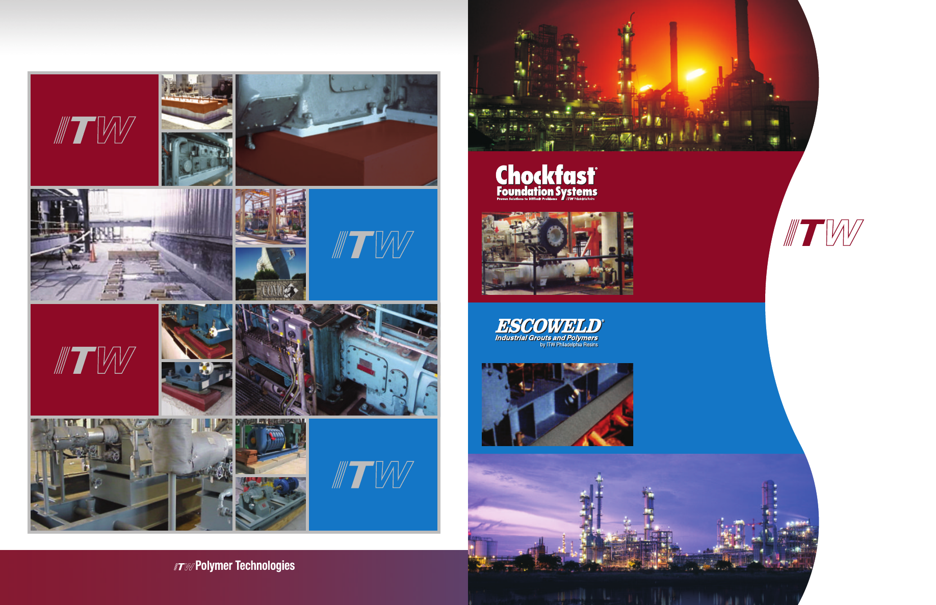
ITW POLYMER TECHNOLOGIES
Industrial Grouts, Polymers and Foundation Systems
130 Commerce Drive, Montgomeryville, PA 18936
(800) 866-8450 • FAX (215) 855-4688
Foundation Systems
with Built-in Reliability
• Permanent Alignment
• Chemical Resistant
• Vibration Damping
• Worldwide Service
For Precise and Permanent
Alignment of all Machinery
• Excellent Vibration Damping
• High Compressive & Bond Strengths
• Superior Resistance to Shrinkage,
Fretting and Shear Loads
• Serviceability within 24 Hours
POLYMER
TECHNOLOGIES
Industrial Grouts, Polymers
and Foundation Systems
For all of your critical
equipment foundation
needs…
©2009 ITW Polymer Technologies