164
S
ur
fa
ce
M
ou
nt
Surface Mount
D
io
de
s
Diodes
S
ur
fa
ce
M
ou
nt
D
io
de
s
Glass/Silicon Passivated Rectifiers
Type PR - Series S1
∆
Features
●
Glass/Silicon Passivated Chip
●
For surface mounted applications
●
Low forward voltage drop
●
Low reverse leakage current
●
High current capability
●
The plastic material carries UL
flammability classification 94V-0
∆
Mechanical Data
●
Case: Molded plastic
●
Polarity: Indicated by cathode band
●
Weight: 0.002 ounces , 0.064 grams
●
Mounting position: Any
Ratings ar 25°C ambient temperature unless otherwise specified.
Single phase, half wave, 60Hz, resistive or inductive load.
For capacitance load, derate current by 20%
∆
Maximum Ratings and Electrical Characteristics
Reverse Voltage - 50 to 1000 Volts
Forward Current - 1.0 Amperes
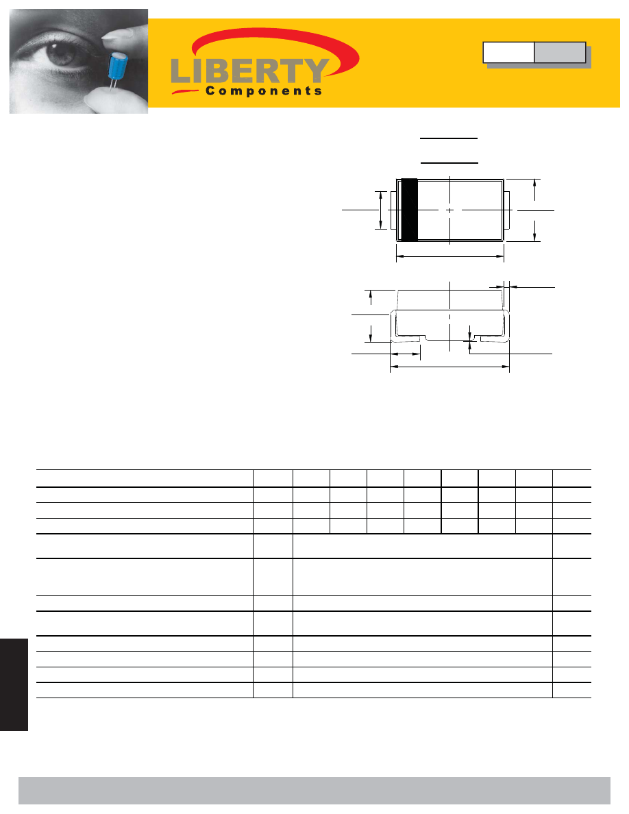
Dimensions in inches and (millimeters)
SMA
.055(1.40)
.062(1.60)
.114(2.90)
.098(2.50)
.181(4.60)
.157(4.00)
.012(.305)
.006(.152)
.002(.051)
.008(.203)
.208(5.28)
.188(4.80)
.079(2.00)
.103(2.62)
.060(1.52)
.030(0.76)
Maximum Recurrent Peak Reverse Voltage
V
RRM
50
100
200
400
600
800
1000
V
Maximum RMS Voltage
V
RMS
35
70
140
280
420
560
700
V
Maximum DC Blocking Voltage
V
DC
50
100
200
400
600
800
1000
V
Maximum Average Forward
Rectified Current
@T
L
=100 °C
Peak Forward Surge Current
8.3ms Single Half Sine-Wave
Super Imposed On Rated Load (JEDEC Method)
Maximum Forward Voltage at 1.0A DC
V
F
V
Maximum DC Reverse Current
@T
J
=25°C
at Rated DC Blocking Voltage
@T
J
=100°C
Typical Junction Capacitance (Note1)
C
J
pF
Typical Thermal Resistance (Note2)
R
θ
JC
°C/W
Operating Temperature Range
T
J
°C
Storage Temperature Range
T
STG
°C
S1K
S1M
S1B
S1D
S1G
S1J
I
FSM
A
I
(AV)
1.0
A
30
S1A
NOTES:1.Measured at 1.0 MHz and applied reverse voltage of 4.0V DC.
2.Thermal resistance junction to lead.
uA
30
-55 to +150
SYMBOL
UNIT
CHARACTERISTICS
I
R
100
5.0
10
1.1
-55 to +150
Type
PR
Glass/Silicon Passivated Rectifiers
Series S1
Liberty Bell Components, Inc. 11631 Seaboard Circle, Stanton, CA 90680 (888)820-8885
Fax: (888)820-8884 email: sales@libertycomponents.com website: www.libertycomponents.com