background image

FUSES 

/ SICHERUNGEN

PFMT

Resettable fuses 

www.schurter.com

19

Surface Mount
PTC-Fuses
Type PFMT

5,4 x 8,5 mm 
High voltage surge
capabilities
Compliance to ITU
K.20/K.21 specifications
Packaged per EIA 486-B 

Agency recognition: 
UL, CSA, TÜV

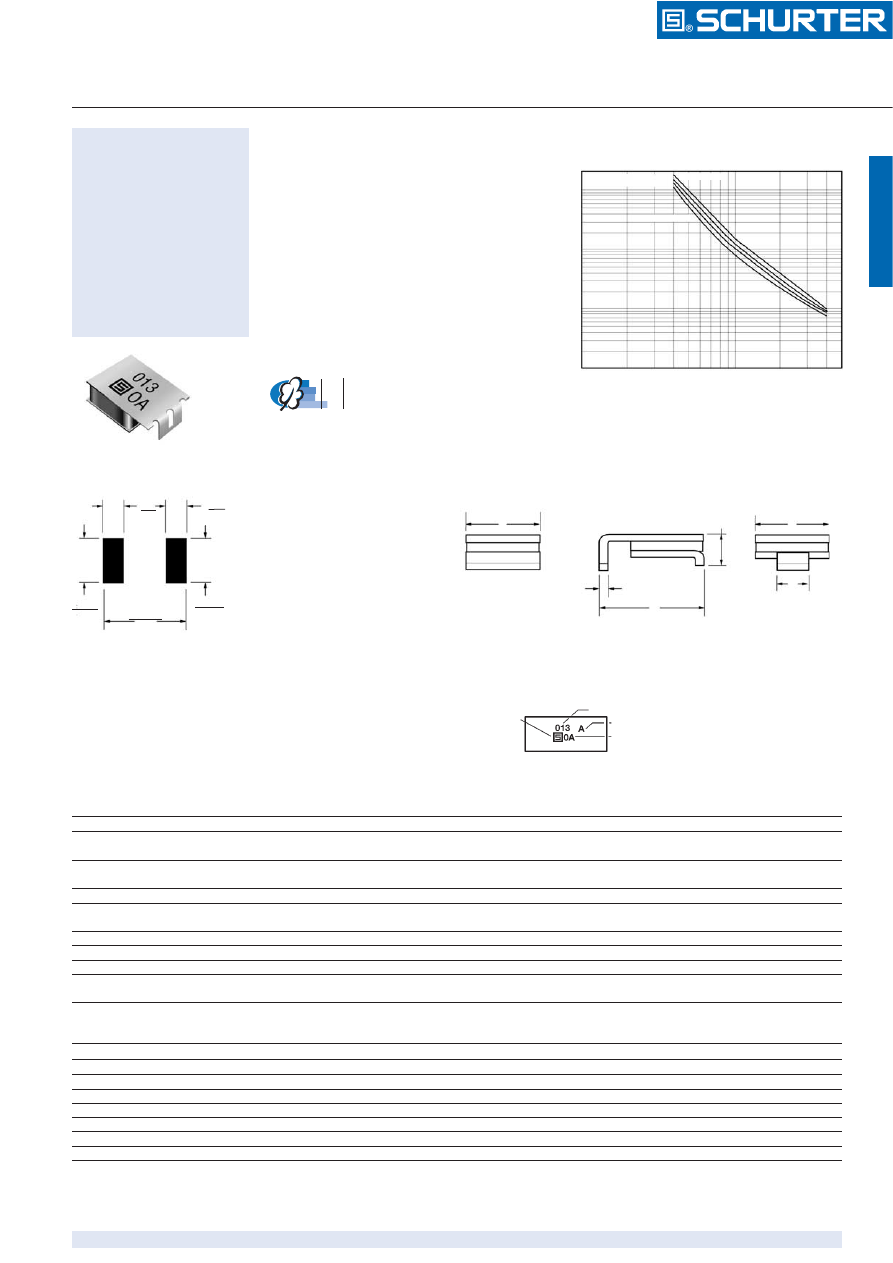
Typical Time to Trip at 23 ˚C 

Time to trip


 (s)

Dimensions 

Applications

Used as a secondary overcurent
protection device in:
• Customer Premise Equipment

(CPE)

• Central Office (CO)
• Subscriber Line Interface

Cards (SLIC)

Test Procedures And Requirements For Model PFMT Series 

Test 

/ Test

Test Conditions 

/ Bedingungen

Accept/Reject Criteria 

Visual/Mech. 

/ visuell/mech.


Verify dimensions and materials 

/ Kontrolle Abmess./Mat. 

Per MF physical description 

Resistance 

/ Widerstand


In still air @ 23°C 

/ bei ruhiger Luft 23 °C

 R

min 

 R 

 R

max

Time to Trip 

/ Trip-Zeit


At specified current, V

max 

23 °C 

/ Bei entspr. Strom

 T 

 max. 

time to trip 


(sec.

)

Hold Current 

/ Haltestrom


30 min. at I

hold 

/ bei Haltestrom


No trip 

/ Keine Auslösung

Trip Cycle Life 

/ Trip-Zyklen


V

max

, I

max

, 100 cycles 

/ Zyklen


No arcing or burning 

Trip Endurance 

/ Zeit im Tripzustand


V

max

, 48 hours 

/ Stunden


No arcing or burning 

Solderability

 / Lötbarkeit


MIL-STD-202F, Method 208F 

/ Methode 208F


95% min. coverage 

Environmental Characteristics 

Operating/Storage Temperature 

/ Einsatz/Lagertemp.

 -45 °C 

to 

+85 °C

Maximum Device Surface Temperature in Tripped State 

/


125 °C

Passive Aging 

/ passive Alterung

 +85 °C, 1000 

hours 

/ Std.

 ± 2% 

typ. resist. change

+60 °C, 1000 

hours 

/ Std.

 ± 3% 

typ. resist. change 

Humidity Aging 

/ Feuchtigkeitsalterung

 +85 °C, 85% R.H. 500 

hours 

/ Std.

 ± 3% 

typ. resist. change 

Thermal Shock 

/ Thermischer Schock

 MIL-STD-202F, Method 107G ±10% 

typ. resist. change 

+125 °C/–55 °C 10 

times 

/ Zyklen

 ±15% 

typ. resist. change 

Solvent Resistance 

/ Lösungsmittel-Beständigkeit

 MIL-STD-202, Method 215B 

No change 

Lead Solerability 

/ Lötbarkeit

 ANSI/J-STD-002

Flammability 

/ Entflammbarkeit

 IEC 695-2-2 

No Flame for 60 sec. 

Vibration 

MIL-STD-883C, Method 2007.1, 

No change 

Condition A 


Typical Part Marking 

Layout may vary 

Manufacturer’s
Trademark 

Part identification 

Date code week 1 of 2000 = 0A (year and week)
week 27 of 2000 = A0 (week and year)

Resistance Bin 

50          75         100

Fault current 

 (A)

0.1                                                    1                                    5

20

10

1

0.1

0.01

PFMT.013.250.A.2

PFMT.013.250.A.2

PFMT.013.250.C.2

PFMT.013.250.2

PFMT.013.250.B.2

1.8
(.071)

4.6
(.181)

9.7
(.382)

1.8
(.071)

4.6
(.181)

Solder pad layouts 

End View /

Endansicht

Side View 

End View /

Endansicht

C

B

D

A

C

E

Schurter_PFMT-html.html
background image

FUSES 

/ SICHERUNGEN

PFMT

Resettable fuses

www.schurter.com

20

Electrical Characteristics 

Type 

/ Typ

 A

B

C

D

E

min.

max.

max.

max.

nom.

nom.

PFMT.013.250.2

8.5

9.4

3.4

7.4

0.3

3.75

(0.335)

(0.370)

(0.134)

(0.291)

(0.011)

(0.148)

PFMT.013.250.A.2

8.5

9.4

3.4

7.4

0.3

3.75

(0.335)

(0.370)

(0.134)

(0.291)

(0.011)

(0.148)

PFMT.013.250.B.2

8.5

9.4

3.4

7.4

0.3

3.75

(0.335)

(0.370)

(0.134)

(0.291)

(0.011)

(0.148)

PFMT.013.250.C.2

8.5

9.4

3.4

7.4

0.3

3.75

(0.335)

(0.370)

(0.134)

(0.291)

(0.011)

(0.148)

Dimensions 

Soldering Profile 

/ Lötprofi

l

How To Order 

PF     MT  .xxx   .xxx   .x   .x

PTC-Fuse 

Style

MT = Surface Mount/
Telecom Component

Hold Current, I

hold 

013 (0.13 Amps)

Max. Interrupt Voltage, V 

250 (250 V)

Resistance Sorted 


A = 6.5-9

B = 9-12

C = 7-12

Packaging Options 
Packaged per EIA 486-B 

2 = 

Tape and reel  

Solder reflow

• Recommended reflow methods: I

R

,

vapor phase oven, hot air oven.

• Devices are not designed to be

wave soldered to the bottom side
of the board.

• Gluing the devices is not recom-

mended.

• Recommended maximum paste

thickness is 0,25 mm (.010 inch).

• Devices can be cleaned using

standard industry methods and
solvents.

Note:

• If reflow temperatures exceed the

recommended profile, devices
may not meet the performance
requirements. 

Rework

• A device should not be reworked.

Thermal Derating Chart-I

hold

/I

trip

(Amps) 

Type 

/ Typ


Ambient Operating Temperature 

–40 ˚C

–20 ˚C

0 ˚C

23 ˚C

40 ˚C

50 ˚C

60 ˚C

70 ˚C

85 ˚C

PFMT.013.250.2

0.21/0.42

0.18/0.37

0.16/0.31

0.13/0.26

0.10/0.23

0.09/0.18

0.08/0.15

0.07/0.12

0.05/0.10

PFMT.013.250.A.2

0.21/0.42

0.18/0.37

0.16/0.31

0.13/0.26

0.10/0.23

0.09/0.18

0.08/0.15

0.07/0.12

0.05/0.10

PFMT.013.250.B.2

0.21/0.42

0.18/0.37

0.16/0.31

0.13/0.26

0.10/0.23

0.09/0.18

0.08/0.15

0.07/0.12

0.05/0.10

PFMT.013.250.C.2

0.21/0.42

0.18/0.37

0.16/0.31

0.13/0.26

0.10/0.23

0.09/0.18

0.08/0.15

0.07/0.12

0.05/0.10

Dimensions in mm/inches 

Type 

/ Typ


Max. Oper. Max. Interrupt Hold Current 

/

 Initial Resistance 

/

 One Hour Nom. Power

Voltage 

/

 Ratings 

/

 Post-Trip Dissipation

Restistance 

/

Volts Volts Amps Amps Ohms Ohms Ohms Watts 

at 

at

 / bei 

23 °C 

at 

/ bei 

23 °C 

at 

/ bei

 23 °C 

at

 / bei 

23 °C 650 V / 23 °C

max.

max.

I

h

min.

max.

max.

PFMT.013.250.2

60

250

3.0

0.13

6.5

12.0

20.0

3.3

PFMT.013.250.A.2

60

250

3.0

0.13

6.5

9.0

20.0

3.3

PFMT.013.250.B.2

60

250

3.0

0.13

9.0

12.0

20.0

3.3

PFMT.013.250.C.2

60

250

3.0

0.13

7.0

10.0

20.0

3.3

Maximum Package Body Temperature (220 °C)

Melting Temperature of Solder (183 °C)

2 Minutes or More

Preheat

Flux Activation

Reflow

Cool

10° to 20 C
per Second

Less than
120 °C per
Second

300

250

200

150

100

50

0

0        30       60            100              150             200              250 

T

emperatur

e (°

C) /

T

Time (Seconde) 

 (s)

Packaged: Tape and reel: 2000 pcs. per reel