background image

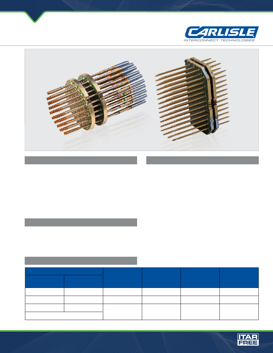
Internal View of Circular and Rectangular TVS Components

Military and aerospace avionics suppliers can design 

electromagnetic pulse (EMP) and lightning protection into 

their modern equipment prior to encountering a catastrophic 

failure. Carlisle Interconnect Technologies (CarlisleIT) can 

offer this protection using less space and weight than a 

conventional Transient Voltage Suppression (TVS) connector. 

Patented design for diode packaging can be used in several 

applications including military aircraft, commercial aircraft 

and helicopter environments.

CarlisleIT packages Transient Voltage Suppression (TVS) 


protection into all of our connector product lines utilizing an 

embedded diode (embedded into a PCB) for space and weight 

savings as well as improved performance.  This innovative 

design resembles (mechanically) a filter assembly so it can be 

packaged into the connector in the same proven manner and 

in tandem if necessary.  TVS connectors are available with 

600 to 2500w diodes to meet some of the highest levels of 

RTCA DO-160 protection, screened to J level standards and 

capable of meeting the environmental requirements of their 

specific Mil-spec’s.

WHY TVS?

KEY FEATURES

Transient Voltage Suppression

TVS Connectors

PERFORMANCE BENEFITS

» Space and weight saving

» Enhanced performance

» Can be packaged in conjunction with filtering

» Lower Cost and Lead times 

DESIGN CAPABILITIES

Power

Standoff Voltage

Breakdown Voltage

UniPolar/

BiPolar

Capacitance

10/100 µSEC

Exponential Pulse

8/20 µSEC

Exponential Pulse

600W

3,600W

5 to 188VDC

7VDC to over 200VDC

Both

<100pF with low cap option

1,500W

9,000W

5 to 188VDC

7VDC to over 200VDC

Both

<100pF with low cap option

40,000W

220,000W

12 to 78 VDC

7VDC to over 200VDC

14 to 91.3VDC

BiPolar

Consult the factory

New Higher Energy to 40kW

Carlisle Interconnect Technologies

 / 102 W. Julie Drive, Tempe, AZ 85283

Toll Free - 480.730.5700 / Fax - 480.730.5800 / 

www.CarlisleIT.com

TVSconnectors-html.html
background image

Semi-Flex

®

 Cable Information

© Carlisle Interconnect Technologies, 2015. All trademarks, service marks and trade names are property of their respective holding companies. All Rights Reserved.

Rev. 010115-POD

TVS Connectors

Carlisle Interconnect Technologies

 / 102 W. Julie Drive, Tempe, AZ 85283

Toll Free - 480.730.5700 / Fax - 480.730.5800 / 

www.CarlisleIT.com

MECHANICAL & ENVIRONMENTAL PERFORMANCE

Test Description

Procedure

Temperature Cycling

Method 1003, MIL-Std-1344, Condition A

Moisture Resistance

MIL-STD-202, Method 106

Durability

500 Matings at a rate of 200 ± 100 cycles per hour

Shock

Method 2004, MIL-STD-1344, Test Condition D 

Vibration

Method 2005, MIL-STD-1344, Test Condition VI, Letter 
J, 8 Hours longitudinal and perpendicular axes

Fluid Immersion

MIL-STD-1344, Method 1016, Fluids (a) and (d)

Salt Spray

MIL-STD-202, Method 101, Condition B

Humidity

MIL-STD-1344, Method 1002, Condition B

Connectors are designed to meet customer specifications 

and the applicable MIL Specification requirements.

TVS CHARTS

0.1

1

10

100

1000

100 ns

1 µs

10 µs

100 µs

1 ms

10 ms

3KW TVS

1.5KW TVS

600W TVS


Pe

ak

 P

ul

se

 P

ow

er

 (

kW

)

PP

M

Non-Repetitive Pulse

Waveform shown in 

Pulse Waveform chart 

T  = 25°C

J

5KW TVS

15KW TVS

0

50

100

150

Half Value-  Ipp

 Ipp                  2

10/1000 µs Waveform

as defined by R.E.A.

t   = 10 µs 

r

t - Time (ms)

0

1.02

.0

3.04

.0

I    

  - 

Pe

ak

 Pu

ls

Cu

rr

en

t, %

I

PP

M

RS

M

T   = 25°C
Pulse Width (t  )
is defined as the point
where the peak current
decays to 50% of I

PPM

d

J

Derate Curve

Peak Power Curve

Peak Pulse Current Curve

100

75

50

25

0

0

Peak

 P

ul

se

 P

ow

er

 (P 


) or

 C

ur

re

nt

 (I 


)

De

ra

ting

 in 

Pr

ecen

ta

ge

, %

50

1001

50

200

T  - Initial Temperature (C°)

J

PP

M

PPM

THE

NEW

THE

OLD

VS.