Liberty Bell Components, Inc. 11631 Seaboard Circle, Stanton, CA 90680 (888)820-8885
Fax: (888)820-8884 email: sales@libertycomponents.com website: www.libertycomponents.com
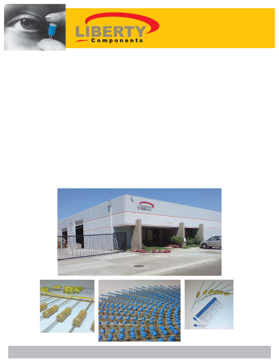
INTRO
Liberty Components is a master distributor of Passive Components located in Southern California serving the
continental United States. We pride ourselves with the best of quality and service. Our reseller and distributor
network though out the United States sells to end-users in the Medical, Telecommunication, and various
Manufacturing industries. All our components are manufactured under strict ISO 9002:94 certified facilities in
Japan, Taiwan, and Korea. We invite you to look though this catalog and call us for samples or quotes of your
passive component needs.
Liberty Components is a stocking master distributor with over 200 million components ready to ship at a
moments notice. Our inventory includes resistors, capacitors and diodes of all values, tolerances and sizes in
both traditional through hole and SMD (Surface Mount Device) packaging.
Liberty Components also specializes in custom OEM passive components. We are able to customize passive
components to your specification under your private brand label. Please call us for your custom OEM compo-
nents.
Please feel free to give us a call. Whether it's 1000pcs, 10 million pcs or customized components, Liberty is your
source to all your passive component needs.