SURFACE MOUNT GLASS PASSIVATED
FAST RECOVERY SILICON RECTIFIER
VOLTAGE RANGE 50 to 600 Volts CURRENT 1.0 Ampere
MAXIMUM RATINGS AND ELECTRICAL CHARACTERISTICS
Ratings at 25
o
C ambient temperature unless otherwise specified.
Single phase, half wave, 60 Hz, resistive or inductive load.
For capacitive load, derate current by 20%.
FM4937L
THRU
FM4933L
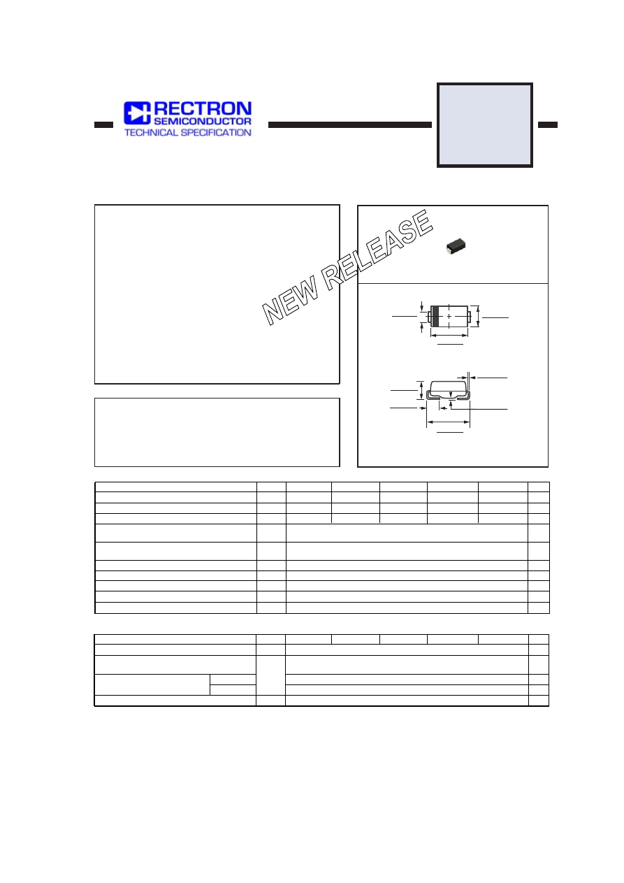
SMAL
MAXIMUM RATINGS
(@ T
A
=25
O
C unless otherwise noted)
ELECTRICAL CHARACTERISTICS
(@T
A
=25
O
C unless otherwise noted)
Dimensions in inches and (millimeters)
RATINGS
Maximum Recurrent Peak Reverse Voltage
Maximum RMS Voltage
Maximum DC Blocking Voltage
Maximum Average Forward Rectified Current
at T
A
= 55
O
C
Peak Forward Surge Current 8.3 ms single half sine-wave
superimposed on rated load (JEDEC method)
Typical Thermal Resistance (Note 1)
Typical Junction Capacitance (Note 2)
SYMBOL
V
RRM
V
DC
I
FSM
C
J
T
STG
V
RMS
UNITS
Volts
Volts
Volts
Amps
1.0
30
70
15
Amps
0
C/W
0
C/W
0
C
Storage Temperature Range
R
q
J L
Typical Thermal Resistance (Note 1)
30
R
q
J A
I
O
pF
Operating Temperature Range
T
J
FM4933L
50
-55 to + 150
150
0
C
FM4934L
FM4935L
FM4936L
FM4937L
FM4933L
FM4934L
FM4935L
FM4936L
FM4937L
100
200
400
35
70
140
280
50
100
200
400
600
600
420
2006-12
CHARACTERISTICS
Maximum Average Reverse Current
Maximum Full Load Reverse Current, Full
cycle Average T
A
=55
O
C
Maximum Reverse Recovery Time (Note 4)
at Rated DC Blocking Voltage
V
F
SYMBOL
I
trr
R
m
A
m
A
m
A
Maximum Instantaneous Forward Voltage at 1.0A DC
Volts
2
50
100
200
nSec
@T
A
= 25
o
C
@T
A
= 100
o
C
UNITS
1.2
NOTES : 1. Thermal Resistance : Mounted on PCB.
2. Measured at 1 MHz and applied reverse voltage of 4.0 volts.
4. Test Conditions: I
F
= 0.5A, I
R
= -1.0A, I
RR
= -0.25A.
3. “Fully ROHS compliant”, “100% Sn plating (Pb-free)”.
FEATURES
* Ideal for surface mounted applications
* Glass passivated device
* Low leakage current
* Metallurgically bonded construction
* Mounting position: Any
* Weight: 0.057 gram
* Epoxy: Device has UL flammability classification 94V-O
MECHANICAL DATA
0.067 ( 1.70 )
0.063 ( 1.60 )
0.012 ( 0.305 )
0.006 ( 0.152 )
0.008 ( 0.203 )
0.004 ( 0.102 )
0.059 ( 1.50 )
0.035 ( 0.89 )
0.209 ( 5.31 )
0.185 ( 4.70 )
0.180 ( 4.57 )
0.160 ( 4.06 )
0.110 ( 2.79 )
0.086 ( 2.18 )
0.067 (1.70 )
0.051 (1.29 )