50
Product specifications contained in this catalogue are subject to change at any time without notice. Please confirm specifications with your order.
【
RoHS
】
W
d
d
L
c
c
H
•
Part Number Description
Example
B
KAMAYA OHM
LTC
•
Dimensions
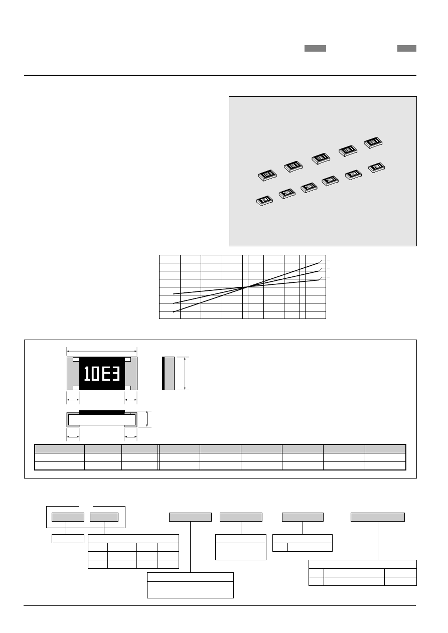
LINEAR POSITIVE T-C CHIP THERMISTORS; RECTANGULAR TYPE
30
•
Termal Characteristics
Temperature Characteristics and Linearity
Ambient Temperature(
°
C)
0
−
40
−
30
−
20
−
10
10
20
30
40
100
60
40
25
0
−
20
−
40
75
∆
R/R(%)
Unit : mm
*Values for reference
1.55
0.10
3.1
0.1
0.6
0.1
0.45
0.20
LTC1/8
LTC1/10
2.0
0.15
0.6
0.1
0.4
0.2
2012
3216
0.2
0.1
Style
W
L
Metric
0805
1206
Inch
H
c
5mg
9mg
d
*Unit weight/pc.
0.3
0.2
0.1
0.3
0.10
0.05
1.25
4,500X10
-6
/
°
C
3,000X10
-6
/
°
C
1,000X10
-6
/
°
C
J
102
LTC
1/8
Product Type
Style
•
Features
1. Linearity of resistance change in wide temperature range.
2. Suitable for temperature compensation, temperature sensing and
controling, and circuit protection applications.
3. Please contact KAMAYA for Halogen free product of LTC series.
4. Stability Class : 5%
Rated resistance and T.C.R. value are marked with 4-digit on the over coating.
e.g. 10E3...
Please contact KAMAYA Sales department for further information.
10 : 1,000
×
10
-6
/
°
C
E3 : 1.5k ohm
Rated Dissipation & Size
Code
1/10
0.1W
2012
3216
1/8
0.125W
Rated Dissipation Metric
0805
1206
Inch
Temperature Coefficient of Resistance
Refer to Ratings Table on next page
e.g.: 30=3,000
×
10
-6
/
°
C
Rated Resistance
E24 Series
e.g.:102=1k ohm
Tolerance on Rated Resistance
J
5%
* Packaging & Standard Qty. (Min.)
Bulk (Loose Package)
B
Paper Tape
1,000pcs.
5,000pcs.
TP
*Refer to Tape and Packaging information on pages 56 and 57.