28
Chip
Resistor
Networks
Product specifications contained in this catalogue are subject to change at any time without notice. Please confirm specifications with your order.
RAC
16
Style
8
C
TP
103
J
U
KAMAYA OHM
1. Highly suitable for the purposes of pull-up and pull-down.
2. Easy to handle because of no specified direction for
mounting due to the symmetrical position of common
terminals.
•Stability Class : 5%
RAC168U
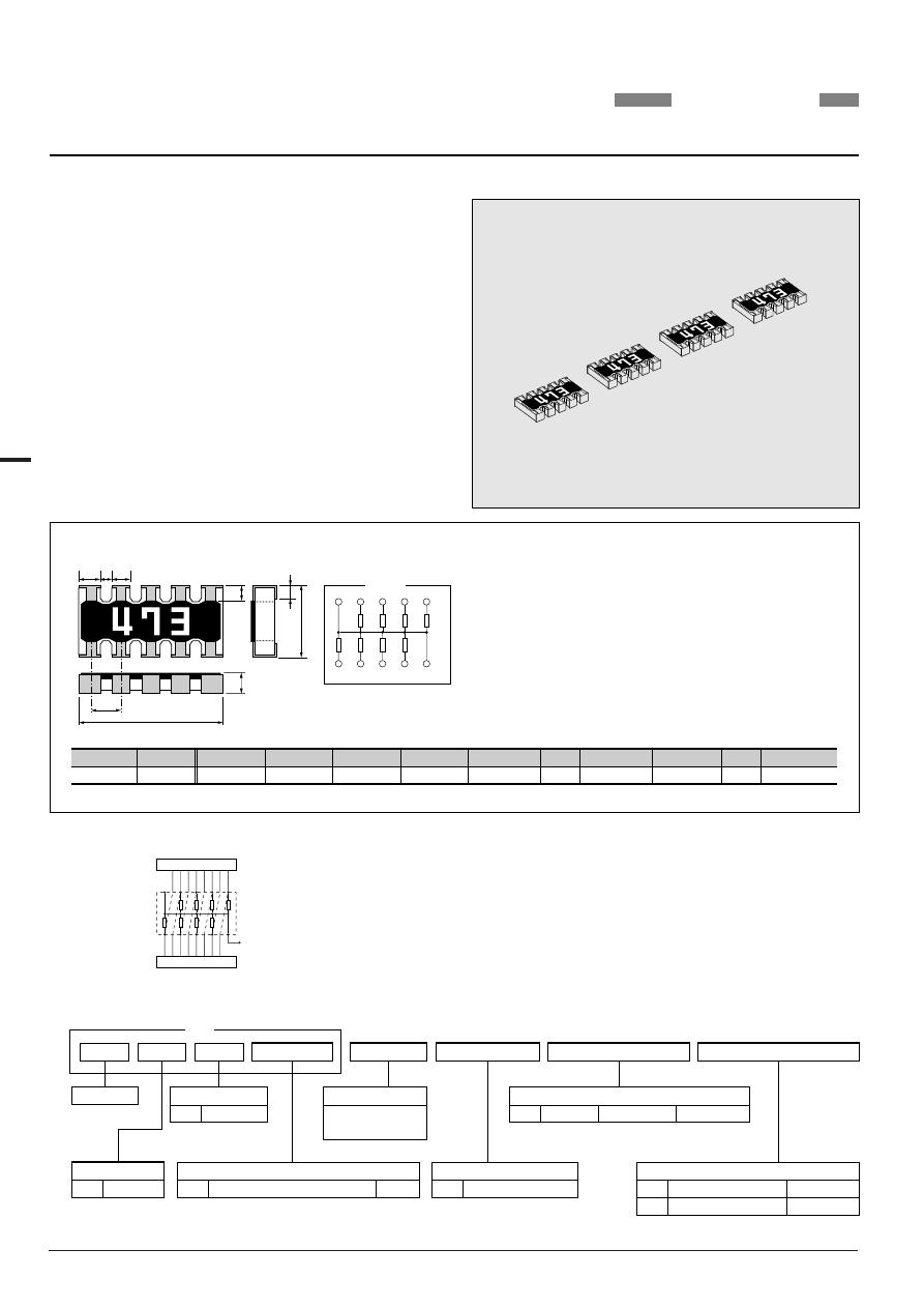
FIXED CHIP RESISTOR NETWORKS; RECTANGULAR TYPE
R
1
R
1
=R
2
=...=R
7
=R
8
R
2
R
3
R
4
R
5
R
6
R
7
R
8
Rated resistance is marked with
3-digit on the over coating.
Circuits
Q
1
Q
2
D
a
L
W
b
H
P
Unit : mm
*Values for reference
0.64
0.3
0.2 0.3
0.15
*Q
2
0.53
0.32
0.10
0.5
0.1
0.32
0.10
1.6
0.1
3.2
0.2
*Unit weight/pc.
*P
b
a
Q
1
7.6mg
H
D
W
L
• Making the parallel 8-Elements
resister for pull-up / pull-down
into one chip.
• Ideal for high density SMT
applications as direct mounting
on the bus line is possible.
Vcc
!
Example
Product Type
* Packaging & Standard Qty. (Min.)
Bulk (Loose Package)
B
Paper Tape
1,000pcs.
5,000pcs.
TP
Tolerance on Rated Resistance
J
5%
Rated Resistance
E24 Series
e.g. : 103=10k ohm
Circuits
U
RAC168U
Common Electrode 2: Same Type
No. of Elements
8
8-Elements
*Refer to Tape and Packaging information on pages 46 and 47.
Terminal Style
With corner
RAC168U
C
Size
16
W:1.6mm
Convex Type