Assembly instructions
6
5
7
1
2
3
7
5
6
L
T
Solder
Solder
Configuration
M0.2
M0.4, M0.5
M0.6 to M1.4
N0.3
N0.4
14.0
4.0
13.0
3.0
12.5
2.5
11.5
3.5
11.5
3.5
Dimensions (mm)
L
T
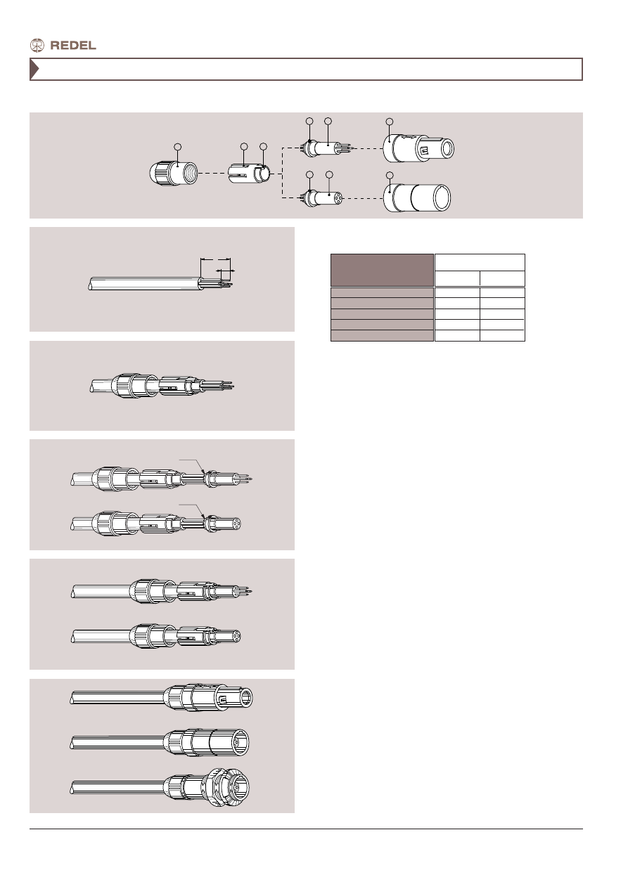
2. Slide the collet nut
➀
and then the collet
➁
onto the cable.
1. Strip the cable according to the lengths given in the
table. Tin the conductors.
3. Solder conductors into contacts, making sure that neither
solder nor flux gets onto the insulator or cable insulation.
4. Slide the collet
➁
forward and locate tag
➂
in the slot
➄
on
the insulator
➅
.
Slide collet nut
➀
over collet
➁
and then push the whole
assembly into the shell
➆
whilst turning it to ensure that the
tag
➂
locates in the inside slot of the shell. Tighten the collet
nut
➀
to the maximum torque of 0.25 Nm.
– Socket mounting nut torque = 1.5 Nm.
For PSU only:
We recommend ONLY the use of VTCS-6 Clear Vibra-tite or
ThreeBond 1401 to secure the connector backnut. The use of
other materials could result in damage to the connector.
The only recommended chemical cleaner is Isopropyl Alcohol.
Solder contacts
26