background image

R

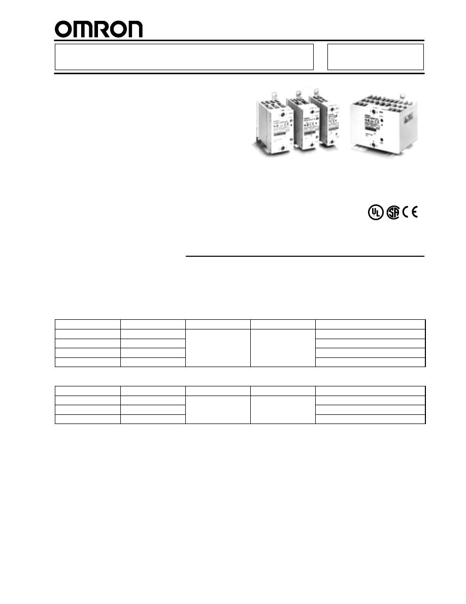
Power Solid State Relays        G3PA

Long Service Life for Circuits that
Cycle Frequently

H

Built-in heat sink increases life and
reliability

H

Voltage turn-on at zero crossing
reduces initial inrush load currents

H

LED indicator turns on when control
power is applied

H

DIN rail mountable

H

Conforms to UL, CSA, VDE and CE
requirements

Ordering Information

J

G3PA RELAYS WITH REPLACEABLE TRIAC OUTPUT CARTRIDGE

D

Current indicator turns red when excessive current is applied

D

Side-by-side dense mounting is possible using built-in linking brackets

24-240 VAC Models

Max. load current

Max. inrush current

Operating voltage

Load voltage

Part number

10 amps

150 amps, 60 Hz

5-24 VDC

24-240 VAC

G3PA-210B-VD DC5-24

20 amps

220 amps, 60 Hz

G3PA-220B-VD DC5-24

40 amps

440 amps, 60 Hz

G3PA-240B-VD DC5-24

60 amps

440 amps, 60 Hz

G3PA-260B-VD DC5-24

200-480 VAC Models

Max. load current

Max. inrush current

Operating voltage

Load voltage

Part number

20 amps

220 amps, 60 Hz

12-24 VDC

200-480 VAC

G3PA-420B-VD-2 DC12-24

30 amps

440 amps, 60 Hz

G3PA-430B-VD-2 DC12-24

50 amps

440 amps, 60 Hz

G3PA-450B-VD-2 DC12-24

me/omron/relays/Heavy-duty_solid_state/omron_relay_solid_state_G3PA-html.html
background image

J

DIN RAIL MOUNTING TRACK

Description

Part number

DIN rail track, 7.3 mm (0.29 in) depth; 50 cm (1.64 ft) length

PFP-50N

DIN rail track, 7.3 mm (0.29 in) depth; 1 m (3.28 ft) length

PFP-100N

End plate

PFP-M

Spacer

PFP-S

Application Example

Load

Heater

Power supply
for load

Direct connection possible

Temperature Controller

Voltage output
terminal 
(for driving SSR)

SSR

Input

Output

Omron’s SSRs offer these advantages over electro-mechanical relays (EMRs):

D

Longer service life with no contacts to wear out

D

Reduced electromagnetic interference

D

Faster response time

D

Vibration and shock resistance

D

No audible noise when switching

D

Enhanced reliability

Specifications

J

RATINGS

Input (at 25

°

C)

Model

Rated voltage

Voltage range

Input current 

Voltage level

impedance

Must operate voltage

Must release voltage

G3PA-210B-VD

5 to 24 VDC

4 to 30 VDC

7 mA max.

4 VDC max.

1 VDC min.

G3PA-220B-VD

G3PA-240B-VD

G3PA-260B-VD

G3PA-420B-VD-2

12 to 24 VDC

9.6 to 30 VDC

7 mA max.

9.6 VDC max.

1 VDC min.

G3PA-430B-VD-2

G3PA-450B-VD-2

          G3PA

G3PA

me/omron/relays/Heavy-duty_solid_state/omron_relay_solid_state_G3PA-html.html
background image

Output

Model

Applicable load

Load voltage

Load current

Inrush current

With Class-1 AC resistive load

G3PA-210B-VD

19 to 264 VAC

0.1 to 10 A

150 A (60 Hz, 1 cycle)

2.4 kW at 240 VAC

G3PA-220B-VD

(50/60 Hz)

0.1 to 20 A

220 A (60 Hz, 1 cycle)

4.8 kW at 240 VAC

G3PA-240B-VD

0.5 to 40 A

440 A (60 Hz, 1 cycle)

9.6 kW at 240 VAC

G3PA-260B-VD

0.5 to 60 A

440 A (60 Hz, 1 cycle)

14.4 kW at 240 VAC

G3PA-420B-VD-2

180 to 528 VAC

0.5 to 20 A

220 A (60 Hz, 1 cycle)

9.6 kW at 480 VAC

G3PA-430B-VD-2

(50/60 Hz)

0.5 to 30 A

440 A (60 Hz, 1 cycle)

14.4 kW at 480 VAC

G3PA-450B-VD-2

0.5 to 50 A

440 A (60 Hz, 1 cycle)

24 kW at 480 VAC

J

CHARACTERISTICS

G3PA

Item

G3PA-
210B-VD

G3PA-
220B-VD

G3PA-
240B-VD

G3PA-
260B-VD

G3PA-
420B-VD-2

G3PA-
430B-VD-2

G3PA-
450B-VD-2

Operate time

1/2 of load power source cycle + 1 ms max. (DC Input, -B models)
1 1/2 of load power source cycle + 1 ms max. (AC Input)

Release time

1/2 of load power source cycle + 1 ms max. (DC Input)
1 1/2 of load power source cycle + 1 ms max. (AC Input)

Output ON voltage
drop

1.6 V (RMS) max.

1.8 V (RMS) max.

Leakage current

5 mA max. at 120 VAC
10 mA max. at 230 VAC

10 mA max. at 120 VAC
20 mA max. at 230 VAC

20 mA max. at 400 VAC

I

2

t

260 A

2

S

810 A

2

S

260 A

2

S

810 A

2

S

Insulation resistance

100 M

 min. at 500 VDC

Dielectric strength

4,000 VAC, 50/60 Hz for 1 min

Vibration resistance

Malfunction: 10 to 55 Hz, 0.75-mm double amplitude (mounted to DIN rail)

Shock resistance

Malfunction: 300 m/s

2

 (mounted to DIN rail)

Ambient temperature

Operating:

–30

°

C to 80

°

C (with no icing or condensation)

Storage:

–30

°

C to 100

°

C (with no icing or condensation)

Approved standards

UL508 File No.E64562, CSA C22.2 (No.14, No.950) File No.LR35535, EN60950 File No. 5915UG

Ambient humidity

Operating: 45% to 85%

Weight

Approx. 
260 g

Approx. 
340 g

Approx. 
460 g

Approx. 
900 g

Approx. 
290 g

Approx. 
410 g

Approx. 
900 g

G3PA

          G3PA

me/omron/relays/Heavy-duty_solid_state/omron_relay_solid_state_G3PA-html.html
background image

Dimensions

Unit: mm (inch)

J

SOLID STATE RELAYS WITH BUILT-IN HEAT SINKS

G3PA-210B-VD

Terminal Arrangement/
Internal Connections

Mounting Holes

Without Terminal Cover

With Terminal Cover

Linking terminal
B1

Linking terminal
B2

4.6 dia.

4.6 x 5.6
elliptical hole

Two, 4.5 dia. or M4 holes

Trigger circuit

Input circuit

Two, M4

Two,
M3.5

100 max.

G3PA

          G3PA

me/omron/relays/Heavy-duty_solid_state/omron_relay_solid_state_G3PA-html.html
background image

G3PA-220B-VD

Terminal Arrangement/
Internal Connections

Mounting Holes

Without Terminal Cover

With Terminal Cover

Linking terminal
B1

Linking terminal
B2

4.6 dia.

4.6 x 5.6
elliptical hole

Two, 4.5 dia. or M4 holes

Trigger circuit

Input circuit

Two, M4

Two,
M3.5

100 max.

G3PA

          G3PA

me/omron/relays/Heavy-duty_solid_state/omron_relay_solid_state_G3PA-html.html
background image

G3PA-240B-VD

Terminal Arrangement/
Internal Connections

Mounting Holes

Without Terminal Cover

With Terminal Cover

Linking
terminal B1

Linking
terminal B2

4.6 dia.

4.6 x 5.6
elliptical hole

Trigger circuit

Input circuit

Two, 4.5 dia. or M4 holes

Two, M5

Two,
M3.5

100 max.

G3PA

          G3PA

me/omron/relays/Heavy-duty_solid_state/omron_relay_solid_state_G3PA-html.html
background image

G3PA-260B-VD
G3PA-450B-VD-2

Terminal Arrangement/
Internal Connections

Mounting Holes

Without Terminal Cover

With Terminal Cover

4.6 x 5.6
elliptical hole

4.6 dia.

Two, 4.5 dia. or M4 holes

Trigger circuit

Input circuit

Two, M5

100 max.

Two, M3.5

110 max.

G3PA

          G3PA

me/omron/relays/Heavy-duty_solid_state/omron_relay_solid_state_G3PA-html.html
background image

90

91

80

4.5

38

7.6

67

2.2
8.8

13.2

8.6

Two, M4

Two, M3.5

90

±

0.2

100
max.

4.6 dia.

37 max.

4.5 x 5.6 elliptic hole

100 max.

Linking
terminal
+B1
Linking
terminal
-B2

25

±

0.2

G3PA-420B-VD-2

Terminal Arrangement/
Internal Connections

Mounting Holes

90

±

0.3

Two, 4.5 dia. or M4

25

±

0.3

Trigger circuit

Input circuit

89

91

4.5

80

38

13

18

13

7.6

67

4.6 dia.

100 max.

47 max.

4.6 x 5.6 elliptic hole

100
max.

90

±

0.2

Linking
terminal
+B1
Linking
terminal
-B2

35

±

0.2

G3PA-430B-VD-2

Terminal Arrangement/
Internal Connections

Mounting Holes

90

±

0.3

35

±

0.3

Two, 4.5 dia. or M4

Trigger circuit

Input circuit

Two, M5

G3PA

          G3PA

me/omron/relays/Heavy-duty_solid_state/omron_relay_solid_state_G3PA-html.html
background image

Precautions

WARNING

Do not touch the terminals (i.e., charged parts) of the G3PB
while power is supplied, otherwise an electric shock may be
received.

If the G3PB is provided with a terminal cover, be sure to attach
the terminal cover to the G3PB before operating the G3PB.

The G3PB and radiator are very hot while power is supplied to
the G3PB.
Do not touch the G3PB or the radiator while power is supplied
to the G3PB or immediately after the G3PB is turned OFF,
otherwise a burn may result.

Do not touch the load terminal of the G3PB immediately after
the G3PB is turned OFF, otherwise an electric shock may be
received due to the residual charge of the built-in snubber cir-
cuit.

Be sure to turn OFF the power supply to the G3PB before wir-
ing, otherwise an electric shock may be received.
Mount the terminal cover to the G3PB after wiring.
Do not touch the terminals of the G3PB while power is sup-
plied, otherwise an electric shock may be received.

The built-in capacitor will be charged as long as power is sup-
plied. Do not touch the terminals of the G3PB unless the G3PB
is turned OFF and the built-in capacitor discharges all of its re-
sidual voltage, otherwise an electric shock may result.

Caution

Do not apply excessive voltage or current to the input or output
circuit of the G3PB, otherwise the G3PB may malfunction or
burn.

Do not use the G3PB unless all the output terminal screws are
tightened securely, otherwise the terminals may generate ex-
cessive heat and the G3PB may burn.

Be sure to provide enough ventilation to the G3PB and the ra-
diator, otherwise the G3PB may generate excessive heat and
the G3PB may burn or the output element may short-circuit.

Be sure to turn OFF the power supply to the G3PB before wir-
ing, otherwise an electric shock may be received.

Be sure to wire or solder the terminals of the G3PB properly,
otherwise the G3PB may generate excessive heat and burn.

If the G3PB is mounted directly to a control panel that is used
as a radiator as well, the control panel must be made of alumi-
num or a steel plate with low thermal resistance.
Do not use any material with high thermal resistance, such as
a wooden plate, otherwise the G3PB may catch on fire or burn.

J

BEFORE ACTUAL OPERATION

The G3PB in operation may cause an unexpected accident.
Therefore it is necessary to test the G3PB under a variety of
conditions that are possible. As for the characteristics of the
G3PB, it is necessary to take into consideration the dispersion
of the characteristics between G3PB Units.

The ratings in this datasheet are tested values in a
temperature range between 15

°

C and 30

°

C, a relative

humidity range between 25% and 85%, and an atmospheric
pressure range between 88 and 106 kPa. It will be necessary
to provide the above conditions as well as the load conditions
if the user wants to confirm the ratings of actual G3PB Units.

J

MOUNTING METHOD

Since the Relay is heavy, firmly mount the DIN track and fix both
ends with End Plates for DIN-track-mounting models.
For direct mounting, firmly mount the Relay on the panel.

Vertical Mounting

Horizontal Mounting

Vertical mounting

Panel

Panel

Note:

Make sure that the load current is 50% of the rated load cur-
rent when the G3PB is mounted horizontally.

Close Mounting

60 mm

30 mm

Note:

Be sure to provide a minimum space of 30 mm horizontally
and 60 mm vertically between adjacent Units.

!

!

G3PA

          G3PA

me/omron/relays/Heavy-duty_solid_state/omron_relay_solid_state_G3PA-html.html
background image

J

WIRING

When using crimp terminals, refer to the terminal clearances
shown below.

Output terminal section

Input terminal section

Be sure that all lead wires are thick enough according to the
current.

Output terminals T1, T2, and T3 are charged regardless of
whether the Unit is a 2- or 3-element model that is turned on or
off. Do not touch these terminals, otherwise an electric shock
may be received.

To isolate the Unit from the power supply, install an appropriate
circuit breaker between the power supply and Unit.

Be sure to turn off the power supply before wiring the Unit.

Terminal L2 and terminal T2 of the 2-element model are internally
short-circuited to each other. Therefore, connect terminal L2 to
the ground terminal of the power supply. If terminal L2 is
connected to a terminal other than the ground terminal, cover all
the charged terminals, such as heater terminals, for the
prevention of electric shock accidents and ground faults.

J

TIGHTENING TORQUE

Refer to the following and be sure to tighten each screw of the
Unit to the specified torque in order to prevent the Unit from
malfunctioning.

Item

Screw terminal

diameter

Tightening torque

Input terminal

M3.5

0.8 N 

S

 m

Output terminal

M4

1.2 N 

S

 m

M5

2.0 N 

S

 m

J

MOUNTING MODELS WITHOUT BUILT-IN
HEAT SINK

Before attaching an external radiator or Heat Sink to the Unit, be
sure to apply silicone grease for heat radiation, such as
Toshiba’s YG6260 or Sinetsu Silicone’s G746, to the surface
where the radiator or Heat Sink is attached.

Be sure to apply the following torque to secure the Unit and external
radiator or Heat Sink for proper heat radiation.

Tightening torque: 2.0 N 

S

 m

J

OPERATING CONDITIONS

Do not apply current exceeding the rated current. Otherwise the
temperature of the Unit may rise excessively.

Be sure to prevent ambient temperature rising due to the heat radi-
ation of the Unit. In the case of enclosed mounting, install a fan so
that the interior of the panel can be fully ventilated.

J

OPERATING AND STORAGE 
ENVIRONMENTS

Do not use or store the Unit in the following places, otherwise the
Unit may malfunction or the characteristics of the Unit may deterio-
rate.

Locations subject to direct sunlight.

Locations subject to ambient operating temperatures outside
the range of –30

°

C to 80

°

C.

Locations subject to ambient operating humidity outside the
range of 45% to 85%.

Locations subject to condensation as the result of severe
changes in temperature.

Locations subject to ambient storage temperatures outside the
range of –30

°

C to 100

°

C.

Locations subject to corrosive or flammable gases.

Locations subject to dust (especially iron dust) or salts.

Locations subject to shock or vibration.

Locations subject to exposure to water, oil, or chemicals.

G3PA

G3PA

me/omron/relays/Heavy-duty_solid_state/omron_relay_solid_state_G3PA-html.html
background image

                                                 Specifications subject to change without notice. 

OMRON ELECTRONICS, INC.

One East Commerce Drive
Schaumburg, IL 60173

1-800-55-OMRON

OMRON CANADA, INC.

885 Milner Avenue
Scarborough, Ontario M1B 5V8

416-286-6465

R

G3PA

          G3PA