16
Disc Ceramic Capacitors
General Specifications - Class III General Purpose
Measured at
1.0 kHz / 0.1 Vrms / 25ºC
Dissipation C
R
≤
22 nF
→
Y5V, Y5U
≤
7.5%
Factor
C
R
> 22 nF
→
Y5V, Y5P
≤
5.0%
Capacitance
Y5P
→
±20% / -20 +50%
Tolerance
Y5U
→
±20% / -20 +80%
Y5V
→
±20% / -20 +80%
Climatic
30 / 085 / 21
Category
Insulation
Y5P
≥
12 M
Ω
Resistance
Y5U
4.7 nF...100 nF
→ ≥
10 M
Ω
@ V
R
200 nF
→ ≥
1 M
Ω
Y5V
≥
100 M
Ω
Dielectric Strength
Between
Vt = 1.25 V
R
NOTE: Charging
leads
current limited
Body
V
R
= 25V Vt = 100V (DC)
to 50 mA
insulation
V
R
= 50V Vt = 150V (DC)
Operating
Temperature
-30... +85
Range (ºC)
PERFORMANCE CHARACTERISTICS CLASS III
Note: Damp Heat Steady State: 90... 95% R.H. 40ºC / 21 days. No voltage to be applied.
DIELECTRIC - CLASS III
A thin dielectric layer is grown on a disc of conductive
ceramic. Very large capacitances can be obtained due to
reduced thickness of this barrier layer and its inherently
high dielectric constant. Due its small dimensions, they
are a less expensive replacement of multilayer ceramic or
polyester capacitors. An equivalent circuit is shown below:
Meets IEC 324 (1970).
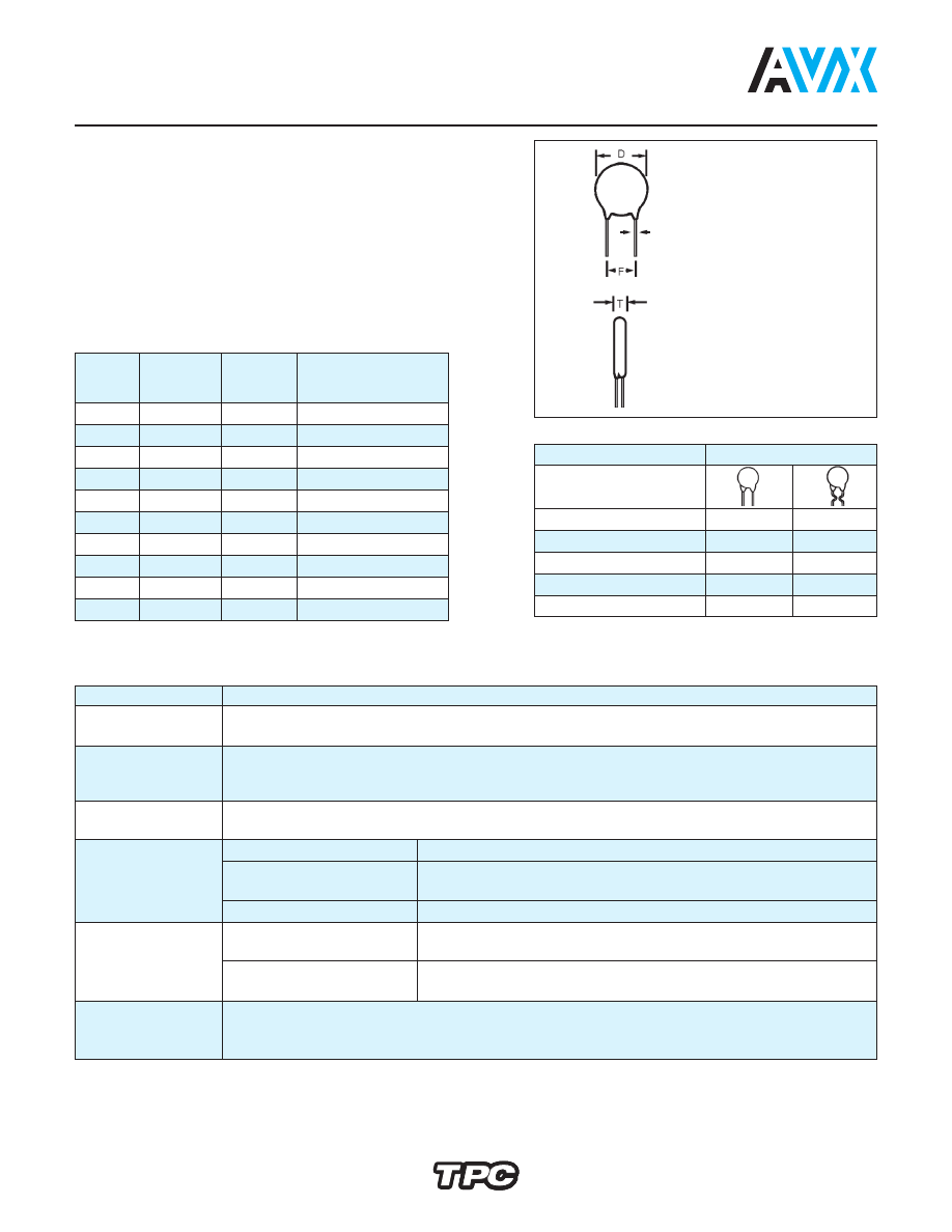
DIMENSIONS
millimeters (inches)
Digit 9
Available
of P.N.
D ± 2
T max.
Lead Spacing
(ø)
(0.079)
A
4.0 (0.157)
3.0 (0.118)
A,B,D,E,O,R
B
5.0 (0.197)
3.0 (0.118)
A,B,D,E,O,R,X
C
6.0 (0.236)
3.0 (0.118)
A,B,C,D,E,O,R,X
D
7.0 (0.276)
3.0 (0.118)
A,B,C,D,E,O,R,X
E
8.0 (0.315)
3.0 (0.118)
A,B,C,D,E,O,R,X
F
9.0 (0.354)
3.0 (0.118)
A,B,C,E,O,R,X
G
10.0 (0.394) 3.0 (0.118)
A,B,C,E,O,R,X
H
11.0 (0.433) 3.0 (0.118)
A,B,C,E,O,R,W
J
13.0 (0.512) 3.5 (0.138)
B,C,R,W
K
15.0 (0.591) 4.0 (0.157)
B,C,R,W
Lead Spacing
Digit 8 of P.N.
F
2.5 (0.100)
D
—
5 (0.200)
A
O
6 (0.250)
E
X
7.5 (0.300)
B
R
10 (0.400)
C
W
Preferred lead spacing
F = 5 (0.197)
Ø = 0.6 ± 0.1
(0.024) (0.004)
millimeters (inches)