background image

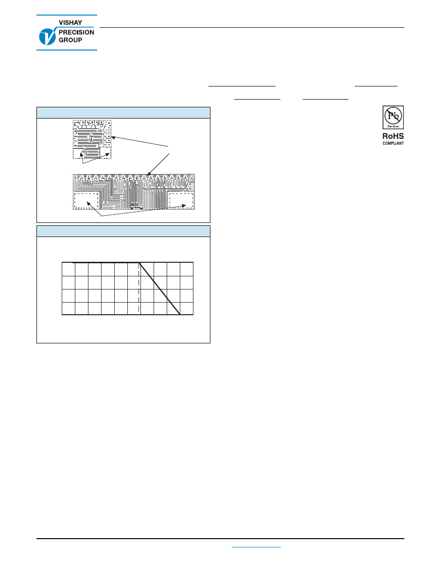
FIGURE 1 - TRIMMING CHIP RESISTORS

V5X5Z

V15X5Z

Gold Plated Pads

Trim Points

Gold Plated Pads

FIGURE 2 - POWER DERATING CURVE

Discrete chips suitable for working temperatures of up to 

+ 200 °C are available on request.

100

75

50

25

0


- 75

- 50

- 25

0

+ 25

+ 50

+ 75 + 100 + 125 + 150 + 175

Ambient Temperature (°C) 

Rated Power (%) 

+ 70 °C

- 55 °C

Ultra High Precision Bulk Metal

®

 Z-Foil Chip Resistors for Use

in Hybrid Circuits with TCR of 0.05 ppm/°C, Tolerance to 0.005 %, 

and Load Life Stability of ± 0.01 % for 10 000 h

V5X5Z, V15X5Z (Z-Foil)

Vishay Foil Resistors


Document Number: 63189

For any questions, contact: 

foil@vishaypg.com

www.vishayfoilresistors.com

Revision: 13-Jan-11

1

FEATURES

Temperature coefficient of resistance (TCR): 


0.05 ppm/°C typical (0 °C to + 60 °C)


0.2 ppm/°C typical (- 55 °C to + 125 °C, + 25 °C ref.)


TCR tracking: to 0.5 ppm/°C

 (1)(2)

TCR characteristic is accomplished automatically 

without selection and regardless of the date of 

manufacture - even if years apart

Hybrid chips with Z-Foil are also available for high 

temperature applications, please contact us for more 

details

Resistance tolerance:


Absolute: to ± 0.01 % (user trimmable to ± 0.005 %) 

Match: to 0.01 %

Power rating: 50 mW to 150 mW at + 70 °C

Load life stability: ± 0.01 % at + 70 °C, 10 000 h at rated 

power 

Resistance range: 50 

Ω

 to 30 k

Ω

 (see table 2) 

Vishay Foil resistors are not restricted to standard values; 

specific “as required” values can be supplied at no extra 

cost or delivery (e.g. 1K2345 vs. 1K)

Short time overload: 

 0.02 % 

Electrostatic discharge (ESD) up to 25 000 V 

Non-inductive, non-capacitive design 

Rise time: 1 ns effectively no ringing 

Thermal stabilization time < 1 s (nominal value achieved 

within 10 ppm of steady state value) 

Current noise: 0.010 µV

RMS

/V of applied voltage (< - 40 dB) 

Non-inductive: < 0.08 µH

Pattern design minimizing hot spots 

The typical pattern and trimming illustrations show that the 

V5X5Z resistor has 16 trimming points, and the V15X5Z has 

20. These trimming points are arranged around the chip 

periphery and are clearly indicated. Trimming to the desired 

resistance value and tolerance is accomplished by cutting 

the trim points, thereby producing specific incremental 

changes in the chip’s resistance value relative to the original 

prevalue; up to + 20 % for the V5X5Z, + 30 % for the 

V15X5Z (not all trim points need be used; the 

Δ

R necessary 

to adjust the pre-value to the desired final value dictates 

which trim points need to be used).
Monitoring of circuit output while “actively” trimming readily 

permits adjustment of the chip to ± 0.005 %.
Actual trimming charts are supplied on request for all 

images.
Vishay precision chip resistors offer an order of magnitude 

of improvement over other chip resistors in hybrid 

applications. With a maximum Temperature Coefficient of 

Resistance (TCR) of ± 2 ppm/°C, selected TCR tracking to 

0.5 ppm/°C and factory supplied resistance tolerances to 

± 0.01 %, they provide the user with accuracy and stability 

not available in other chip resistor products. If desired they 

can be user trimmed to any value within ± 0.005 %, where 

the value remains stable after trimming. Load life stability is 

0.05 % 

Δ

R maximum under full rated power for 2000 h at 

+ 70 °C. 

The Vishay precision trimming system allows for adjustment 

to precise resistance values without concern over 

mechanical override and control problems encountered in 

laser or air abrade trimming of solid geometry resistance 

patterns. This ability to trim resistor chips to tolerance levels 

never before available to hybrid manufacturers, now gives a 

project manager the ability to increase the value-added level 

of their hybrid services. More of the profit thus available can 

be retained within the facility. Now, instead of buying 

precision resistors in separate packages or modules (which 

require additional PC board real estate) and integrating them 

into a system, the project manager can utilize Vishay 

precision resistor chips or matched sets to manufacture the 

entire hybrid circuit in-house. Eliminates the need to “pin-out” 

for precision resistor requirements because the precision 

resistors are inside - part of the hybrid microcircuit design.
Vishay precision chip resistors are available either factory- 

trimmed to exact resistance values (option T) or ready for 

user trimming (option U); user trimming can be done either 

before or after bonding - using standard epoxies - onto the 

hybrid circuit substrate using standard laser, air abrade, or 

manual adjustment techniques. However care should be 

taken that no carbonization occurs when laser trimming.

v5x5zv15-html.html
background image

TABLE 1 - TOLERANCE AND TCR VS. RESISTANCE VALUE

(1)

VALUE

(

Ω

)

STANDARD TOLERANCE

(%)

TYPICAL TCR AND MAX SPREAD

- 55 °C to + 125 °C, + 25 °C Ref. (ppm/°C)

(2)

500 to 30K

± 0.01

± 0.2 ± 1.8

100 to < 500

± 0.02

50 to < 100

± 0.02

± 0.2 ± 2.8

V5X5Z, V15X5Z (Z-Foil)

Vishay Foil Resistors


www.vishayfoilresistors.com

For any questions, contact: 

foil@vishaypg.com

Document Number: 63189

2

Revision: 13-Jan-11

Note

(1)

For tighter performances or high temperature applications, please contact application engineering.

(2)

The TCR results show 4 terminal measurements. To view TCR results for 2 terminal measurements and for different gold wire lengths, refer 
to the nomogram on page 6.

FIGURE 4 - DIMENSIONS 

in inches (millimeters)

0.020 ± 0.005

(0.508 ± 0.127)

0.150 ± 0.005

(3.81 ± 0.127)

0.050

±

0.005

(1.27

±

0.127)

+ 0.001
- 0.004

+0.025
- 0.102

0.019

0.483

(                  )

0.005 ± 0.004

(1.27 ± 0.102)

+ 0.001
- 0.004

+0.025
- 0.102

0.029

0.737

(                  )

0.050 ± 0.005

(1.27 ± 0.127)

0.050

±

0.005

(1.27

±

0.127)

0.034

(0.864)

Nominal

0.008

(0.203)

Nominal

0.008

(0.203)

Nominal

Square

0.008

(0.203)

Nominal

0.020 ± 0.005

(0.508 ± 0.127)

V15X5Z

V5X5Z

FIGURE 3 - Z-FOIL TYPICAL RESISTANCE/ TEMPERATURE CURVE

+ 500 

+ 200 

+ 100 

0

- 100 

- 200 

- 300 

- 500 

- 55

- 25

+ 25

+ 60

+ 75

+ 100

+ 125

Δ

R

R

(ppm)

0

0.05 ppm/°C 

- 0.1 ppm/°C

0.1 ppm/°C 

0.14 ppm/°C 

0.2 ppm/°C 

- 0.16 ppm/°C 

- 400 

+ 300 

+ 400 

Ambient Temperature (°C) and TCR Chord Slopes for

Different Temperature Ranges

v5x5zv15-html.html
background image

TABLE 2 - PRECISION CHIP RESISTOR SPECIFICATIONS

Resistance range

50 

Ω

 to 5 k

Ω

 (model V5X5Z) 


50 

Ω 

to 30 k

Ω

 (model V15X5Z) 

TCR


(- 55 °C to + 125 °C, + 25 °C Ref. (ppm/°C)

See Table 1

Trimming range 


(Approximate adjustment capability)

0 to 1.2 x nominal prevalue (V5X5Z)*


0 to 1.3 x nominal prevalue (V15X5Z) 

Note

* The V5X5Z chips are being gradually redesigned for a higher trimming factor - 

1.3 or more instead of 1.2. For information about the availability of a specific 

resistance value, contact the factory.

Resistance tolerance

Option T (trimmed to value at Vishay)*


± 0.01 %; ± 0.02 %; ± 0.05 %; ± 0.1 %; ± 0.25 %; ± 0.5 %; ± 1 %; ± 5 % 


Option U (for user trimming to any value within ± 0.005 %) 


G.F. = Good for values


Note


*


See table 1 for resistance/tolerance limits

Power rating 


(at + 70 °C ambient temperature), (see figure 4)

V5X5Z: 0.05 W (15 V maximum)


V15X5Z: 0.1 W (50 V maximum)

High frequency operation 


Rise time 


Inductance 


Capacitance


1 ns without ringing


0.1 µH maximum; 0.08 µH typical 


1.0 pF maximum; 0.5 pF typical

Current noise

< 0.010 µV

RMS

/V of applied voltage (< - 40 dB)

Voltage coefficient

< 0.1 ppm/V

Working voltage

15 V (model V5X5Z) 


50 V (model V15X5Z) 

Termination pads

Gold: 50 µ

"

 to 100 µ

thick

TABLE 3 - ENVIRONMENTAL PERFORMANCE COMPARISON

TYPICAL VISHAY

MAXIMUM

Test group I


Thermal shock

± 0.02 %

± 0.04 %

Test group II


Low temperature operation


Short time overload


High temperature exposure


Resistance to bonding exposure

± 0.005 %

± 0.02 %

± 0.02 %

± 0.02 %

± 0.01 %

± 0.04 %

± 0.05 %

± 0.05 %

Test group III


Moisture resistance

± 0.03 %

± 0.1 %

Test group IV (Load Life Stability)


2000 h at + 70 °C


10 000 h at + 70 °C

± 0.005 %

± 0.01 %

± 0.015 %

± 0.05 %

V5X5Z, V15X5Z (Z-Foil)

Vishay Foil Resistors


Document Number: 63189

For any questions, contact: 

foil@vishaypg.com

www.vishayfoilresistors.com

Revision: 13-Jan-11

3

Notes

(1)

TCR tracking is a measure of the similarity of resistance value change in two or more resistors which are undergoing the same 
temperature changes. Tracking could be expressed as the difference in the temperature coefficients of the resistors, expressed in ppm/°C 
as (

Δ

R

1

/R

1

 - 

Δ

R

2

/R

2

) x 10

-6

/

Δ

T °C.

(2)

Selected TCR tracking is available for specially ordered lots of resistors. The selected TCR tracking can be 3, 2, 1 and as close as 0.5 ppm/°C 
throughout the full temperature range. Should close TCR tracking be required for differing resistance values, contact the factory.

v5x5zv15-html.html
background image

V5X5Z, V15X5Z (Z-Foil)

Vishay Foil Resistors


www.vishayfoilresistors.com

For any questions, contact: 

foil@vishaypg.com

Document Number: 63189

4

Revision: 13-Jan-11

To acquire a precision resistance value, the Bulk Metal Foil chip is 
trimmed by selectively removing built-in “shorting bars.” To increase 
the resistance in known increments, marked areas are cut, 
producing progressively smaller increases in resistance. This 
method reduces the effect of “hot spot” and improves the long term 
stability of the hybrid chips.

FIGURE 5 - TRIMMING TO VALUES


(conceptual illustration)

Mutual Inductance
Reduction due
to Change in
Current Direction

Current Path

Before Trimming

Note:

 Foil shown in black, etched spaces in white

Interloop Capacitance
Reduction in Series

Trimming Process

Removes this Material

from Shorting Strip Area

Changing Current Path

and Increasing

Resistance

Current Path

After Trimming

TABLE 4 - GLOBAL PART NUMBER INFORMATION

 (trimmed option) 

(1)(2)

NEW GLOBAL PART NUMBER:  Y4033249R000Q0W  (preferred part number format)

DENOTES PRECISION

VALUE

CHARACTERISTICS

Y

R

 = 

Ω 

K

 = k

Ω

0

 = standard


1 to 999

 = custom

PRODUCT CODE

RESISTANCE TOLERANCE

PACKAGING

Trimmed 

(2)

:


4033

= V5X5ZT


4034

= V15X5ZT

T

= ± 0.01 %


Q

= ± 0.02 %


A

= ± 0.05 %


B

= ± 0.1 %


C

= ± 0.25 %


D

= ± 0.5 %


F

= ± 1.0 %


J

= ± 5.0 %

W

 = waffle pack

FOR EXAMPLE: ABOVE GLOBAL ORDER Y4033 249R000 Q 0 W:
TYPE: V5X5Z trimmed


VALUE: 249.0 

Ω 

ABSOLUTE TOLERANCE: ± 0.02 %


PACKAGING: waffle pack


HISTORICAL PART NUMBER:  V5X5ZT  249R00  Q  W  (will continue to be used)

V5X5ZT

249R00

Q

W

MODEL

OHMIC VALUE

RESISTANCE TOLERANCE

PACKAGING

V5X5ZT


V15X5ZT

249R00

 = 249.0 

Ω

T

= ± 0.01 %


Q

= ± 0.02 %


A

= ± 0.05 %


B

= ± 0.1 %


C

= ± 0.25 %


D

= ± 0.5 %


F

= ± 1.0 %


J

= ± 5.0 %

W

 = waffle pack

Notes

(1)

For non-standard requests, please contact application engineering.

(2)

VISHAY to supply chips trimmed to the purchaser’s exact resistance and tolerance specifications, ready for insertion into a hybrid microcircuit 

with no further processing other than bonding and termination. Specify exact resistance value(s) and tolerance(s).

0

3

3

2

9

R

0

4

Y

4

Q

0

0

W

0

v5x5zv15-html.html
background image

TABLE 5 - GLOBAL PART NUMBER INFORMATION

 (untrimmed option) 

(1)(2)

NEW GLOBAL PART NUMBER:  Y4036759R0000W  (preferred part number format)

DENOTES PRECISION

GOOD FOR VALUE 

(2)

PACKAGING

Y

R

 = 

Ω 

K

 = k

Ω

W

 = waffle pack

PRODUCT CODE

CHARACTERISTICS

Untrimmed 

(2)

:


4036

= V5X5ZU


4037

= V15X5ZU

0

 = standard


1 to 999

 = custom

FOR EXAMPLE: ABOVE GLOBAL ORDER Y4036 759R000 0 W:
TYPE: V5X5Z untrimmed


GOOD FOR VALUE: 759.0 

Ω 

PACKAGING: waffle pack


HISTORICAL PART NUMBER:  V5X5ZU  759R00  W  (will continue to be used)

V5X5ZU

759R00

W

MODEL

GOOD FOR VALUE

PACKAGING

V5X5ZU


V15X5ZU

759R00

 = 759.0 

Ω

W

 = waffle pack

V5X5Z, V15X5Z (Z-Foil)

Vishay Foil Resistors


Document Number: 63189

For any questions, contact: 

foil@vishaypg.com

www.vishayfoilresistors.com

Revision: 13-Jan-11

5

Notes

(1)

For non-standard requests, please contact application engineering.

(2)

To order user trimmable chips specify the final resistance value desired.

0

3

6

7

9

R

0

5

Y

4

0

0

W

0

v5x5zv15-html.html
background image

V5X5Z, V15X5Z (Z-Foil)

Vishay Foil Resistors


www.vishayfoilresistors.com

For any questions, contact: 

foil@vishaypg.com

Document Number: 63189

6

Revision: 13-Jan-11

EFFECTS OF GOLD WIRE

The bonding of the gold wires to the chip has an effect on the overall resistance and on the temperature coefficient, according to 

the length of wire used. 


The nomogram below shows the effect on both parameters with varying lengths of 0.001" (0.0254 mm) diameter gold wire. 

NOMOGRAM

Change of resistance and TCR due to a length L of gold wire added at wire bonding.


500

360

250

160
120

90

62.5

40

22.5

10

50
23
16

10.5

6

4

2.25
1.40
0.82
0.47

0.30
0.16

0.11

600
350
225

130

85
41
25
16
10

6

1900
1100
610
400

230

150

85
53
31
18

11
6.1
4.2
2.3
1.5
0.85

0.50
0.32
0.15
0.10
0.06
0.04

0.02

1

1.4

2.2

3.2
4

6.2

9

12.2

16

25

36

49
64

81
100

144

225

324
400

625

900

1.2K
1.6K

2.5K

3.6K

4.9K

6.4K
8.1K
10K

14.4K

22.5K

32.4K
40K

ppm

%

A

B

R

Δ

TCR

ppm/°C

Δ

 R
R

L

thousandths of an inch
total length of 2 gold
wires of 0.001" diameter

nominal resistance of
chip as measured on its
pads (

Ω

)

EXAMPLE:

Total length of wires L = 0.100" (point A on left scale)
Resistance of chip R = 200 

Ω

 (point B on right scale)

Read on intersection of line as with central scale:
    On left side - change of resistance:


Δ

      R
On right side - change of TCR:


Δ

TCR = + 2.3 ppm/°C

Nomogram based on the following specs for gold wire:
• 1.2 

Ω

/inch for 0.001" (0.0254 mm) diameter wire

• TCR 3900 ppm/°C

= 600 ppm

v5x5zv15-html.html
background image

Vishay Precision Group

Document No.: 63999

Revision: 27-Apr-2011

www.vishaypg.com

1

Legal Disclaimer Notice

Disclaimer

Legal Disclaimer Notice

Disclaimer

Document No.: 63999

Revision: 27-Apr-2011

ALL PRODUCTS, PRODUCT SPECIFICATIONS AND DATA ARE SUBJECT TO CHANGE WITHOUT NOTICE.

Vishay Precision Group, Inc., its affiliates, agents, and employees, and all persons acting on its or their 
behalf (collectively, “Vishay Precision Group”), disclaim any and all liability for any errors, inaccuracies or 
incompleteness contained herein or in any other disclosure relating to any product.

The product specifications do not expand or otherwise modify Vishay Precision Group’s terms and 
conditions of purchase, including but not limited to, the warranty expressed therein.

Vishay Precision Group makes no warranty, representation or guarantee other than as set forth in the terms 
and conditions of purchase. 

To the maximum extent permitted by applicable law, Vishay Precision 

Group disclaims (i) any and all liability arising out of the application or use of any product, (ii) any and 
all liability, including without limitation special, consequential or incidental damages, and (iii) any and 
all implied warranties, including warranties of fitness for particular purpose, non-infringement and 
merchantability.

Information provided in datasheets and/or specifications may vary from actual results in different 
applications and performance may vary over time. Statements regarding the suitability of products for 
certain types of applications are based on Vishay Precision Group’s knowledge of typical requirements that 
are often placed on Vishay Precision Group products. It is the customer’s responsibility to validate that a 
particular product with the properties described in the product specification is suitable for use in a particular 
application.

No license, express, implied, or otherwise, to any intellectual property rights is granted by this document, or 
by any conduct of Vishay Precision Group.

The products shown herein are not designed for use in life-saving or life-sustaining applications unless 
otherwise expressly indicated. Customers using or selling Vishay Precision Group products not expressly 
indicated for use in such applications do so entirely at their own risk and agree to fully indemnify Vishay 
Precision Group for any damages arising or resulting from such use or sale. Please contact authorized 
Vishay Precision Group personnel to obtain written terms and conditions regarding products designed for 
such applications.

Product names and markings noted herein may be trademarks of their respective owners.