background image

50

01-04

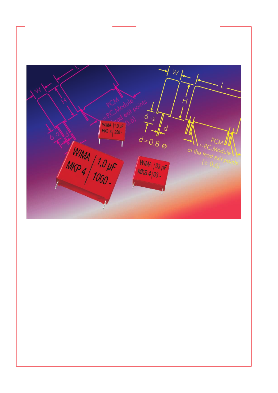
WIMA Kondensatoren für erhöhte Anforderungen umfassen ein
breites Kapazitäts- und Spannungsspektrum und stehen als
Polyester-, Polypropylen- oder Mischdielektrikum-Ausführungen
in metallisierter oder Film/Folien-Bauweise zur Verfügung.

Bei metallisierten Kondensatoren (Aufbau siehe Seite 49) wird
eine dünne Metallschicht als Elektrode auf eine Kunststofffolie auf-
gedampft. Somit können Kondensatoren mit einem sehr günstigen 
Kapazitäts/Volumen-Verhältnis hergestellt werden. Den höchsten 
C-Wert erreicht der WIMA MKS 4 mit 100 

m

F/63 V-. Eine weitere

spezifische Eigenschaft metallisierter Kondensatoren ist die hervor-
ragende Selbstheilfähigkeit. Im Bereich eines elektrischen Durch-
schlages verdampft die Metallschicht und die betroffene Stelle 
wird isoliert. Dadurch bleibt der Kondensator voll funktionsfähig.

Beim Film/Folien-Aufbau wird die Elektrode nicht aufgedampft
sondern als Metallfolie zusammen mit dem Dielektrikum gewickelt.
Die so gefertigten Bauelemente besitzen aufgrund des niedrigeren
Serienwiderstandes eine hervorragende Impuls- bzw. Strombelast-
barkeit sowie einen sehr hohen Isolationswiderstand.

WIMA Kondensatoren für erhöhte Anforderungen stehen im 
Wertebereich von 100 pF bis 33 

m

F mit Spannungsreihen bis 

2000 V- zur Verfügung. Auf Kundenwunsch können größere 
Bauformen als Sonderanfertigung in Vierdraht-Ausführung oder 
mit Anschlußlaschen gefertigt werden.

WIMA capacitors for demanding requirements cover a wide 
range of capacitances and voltages and are available with 
polyester, polypropylene or mixed dielectric as metallized or 
film/foil types of construction.

For metallized capacitors (construction see page 49) a thin metal 
coating serving as electrode is applied to the plastic film. This 
method makes it possible to produce capacitors with a very 
favourable capacitance/volume ratio. The WIMA MKS 4, with 
100 

m

F/63 VDC, offers the highest C-rating in the WIMA range.

A further specific characteristic of metallized capacitors is the
excellent self-healing ability. In the case of an electric breakdown
the applied metal layer evaporates. The affected area is isolated
and the capacitor continues to function properly.

In the case of film/foil types, the electrode is not applied as for 
the metallized capacitors, but is wound with the dielectric as a 
metal foil. Due to their lower series resistance, the components 
produced this way have excellent pulse and current carrying 
capacities, as well as a very high insulation resistance.

WIMA capacitors for stringent requirements are available with 
values ranging from 100 pF through 33 

m

F with voltage ratings 

up to 2000 VDC. In accordance with customer requirements, 
larger box sizes can be supplied as 4-lead versions. Types with 
terminating tabs can also be manufactured on request.

Kondensatoren für 
erhöhte Anforderungen

Capacitors for
stringent requirements

wima_stringent_requirements-html.html
background image

51

01-04

WIMA MKS 4

Metallisierte Polyester-Kondensatoren
für erhöhte Anforderungen

˜

  Für  alle  Standardanwendungen  in  Rastermaßen  

 7,5 mm. 

˜

 Großes Kapazitätsspektrum bis 100 

m

F

und Spannungsreihen bis 2000 V-. 

˜

 Niedriger ESR. 

˜

  Speicherkondensator  ohne  Lebensdauerbegren-

zung selbst bei hohen Temperaturen. 

˜

 Gegurtet lie-

ferbar bis einschl. Bauform 15 x 26 x 31,5/RM 27,5.

Metallized polyester capacitors for 
stringent requirements

˜

  For  all  standard  applications  in  PCM 

  7.5  mm. 

˜

 Wide capacitance range up to 100 

m

F and voltage 

ranges  up  to  2000  VDC. 

˜

  Low  ESR. 

˜

  Reservoir 

capacitor  with  unlimited  life  expectancy  even  at 
high temperatures. 

˜

 Available taped and reeled up

to and including case size 15 x 26 x 31.5/PCM 27.5.

Technische Angaben

Dielektrikum:

 Polyäthylenterephthalat-Folie.

Beläge:

 Aluminium, aufmetallisiert.

Umhüllung:

 Flammhemmendes Kunststoffgehäuse, UL 94 V–0. 

Farbe: Rot. Aufdruck: Schwarz. Epoxidharzverguß: Rot.

Temperaturbereich:

 –55

)

 C bis +100

)

 C.

Prüfungen: 

Nach IEC 60384-2 bzw. EN 130 400.

Prüfklasse:

 55/100/56 nach IEC.

Isolationswerte

 bei +20° C:


U

N

        U

meß

          C 

 0,33 

m

F         0,33 

m

F < C 

 33 

m

F


     50 V-      10 V         

 5 

 10

3

 M

V


1500 s (M

V


m

F)


                      Mittelwert: 3 

 10

4

 M

V

   Mittelwert: 4500 s


     63 V-    50 V


 1 

 10

4

 M


3000 s (M

V


m

F)


       Mittelwert: 5 

 10

4

 M

Mittelwert: 6000 s

    100 V- 

100 V


 1,5 

 10

4

 M


5000 s (M

V


m

F)


       Mittelwert: 5 

 10

4

 M

Mittelwert: 15 000 s


250 V- 

100 V


 3 

 10

4

 M


10 000 s (M

V


m

F)


       Mittelwert: 1 

 10

5

 M

Mittelwert: 40 000 s

Nach IEC 60384-2 Grade 1 und EN 130 400.
Meßzeit: 1 min.

Kapazitätstoleranzen:


±

 20 %, 

±

 10 %, 

±

 5 %.

Verlustfaktoren

 bei +20

)

 C: tan 

d

 Gemessen bei  C 

 0,1 

m

F  0,1 

m

<

 C 

 1,0 

m

>

1,0 

m

F


    1 k Hz 

   8 

 10

-3


   8 

 10

-3


 10 

 10

-3


  10 kHz 

 15 

 10

-3


 15 

 10

-3


100 kHz 

 30 

 10

-3


– 

Prüfspannung:

 1,6 U

N

 , 2 s.

Schwingen:

 6 h bei 10 . . . 2000 Hz und 0,75 mm Auslenkung

bzw. 10 g nach IEC 60068-2-6.

Unterdruck:

 1 kPa = 10 mbar nach IEC 60068-2-13.

Stoßtest:

 4000 Stöße mit 390 m/s

2

 nach IEC 60068-2-29.

Spannungsderating:

 Die zulässige Spannung vermindert sich ge-

genüber der Nennspannung bei Gleichspannungsbetrieb ab +85

)

C,

bei Wechselspannungsbetrieb ab +75

)

 C um 1,25 % je 1 K.

Kurven siehe Seite 6.

Impulsbelastung

 bei vollem Spannungshub:

Technical Data

Dielectric:

 Polyethylene-terephthalate film.

Capacitor electrodes:

 Vacuum-deposited aluminium.

Encapsulation:

 Flame retardent plastic case, UL 94 V–0. 

Colour: Red. Marking: Black. Epoxy resin seal: Red.

Temperature range:

 –55

)

 C to +100

)

 C.

Test specification: 

In accord. with IEC 60384-2 and EN 130 400.

Test category:

 55/100/56 in accordance with IEC.

Insulation resistance

 at +20° C:


U

r

       U

test

         C 

 0.33 

m

F           0.33 

m

F < C 

 33 

m

F


     50 VDC  10 V         

 5 x 10

3

 M

V


1500 sec (M

V

 x 

m

F)


                  Mean value: 3 x 10

4

 M

V

Mean value: 4500 sec


     63 VDC  50 V


 1 x 10

4

 M

V    


3000 sec (M

V

 x 

m

F)


                  Mean value: 5 x 10

4

 M

V

Mean value: 6000 sec

   100 VDC 100 V


 1.5 x 10

4

 M

V   


5000 sec (M

m

F)


                  Mean value: 5 x 10

4

 M

V

Mean value:15000 sec


250 VDC 100 V


 3 x 10

4

 M

V    


10 000 sec (M

m

F)


                  Mean value: 1 x 10

5

 M

V

Mean value:40000sec

In accordance with IEC 60384-2 grade 1 and EN 130 400.
Measuring time: 1 min.

Capacitance tolerances:


±

 20 %, 

±

 10 %, 

±

 5 %.

Dissipation factors

 at +20

)

 C: tan 

d


at f 

 0.1 

m

F  0.1 

m

<

 C 

 1.0 

m

>

1.0 

m

F


    1 k Hz 

   8 x 10

-3


   8 x 10

-3


 10 x 10

-3


  10 k Hz 

 15 x 10

-3


 15 x 10

-3


100 kHz 

 30 x 10

-3


– 

Test voltage:

 1.6 U

r

 , 2 sec.

Vibration:

 6 hours at 10 . . . 2000 Hz and 0.75 mm displacement 

amplitude or 10 g in accordance with IEC 60068-2-6.

Low air density:

 1 kPa = 10 mbar in accord. with IEC 60068-2-13.

Bump test:

 4000 bumps at 390 m/sec

2

 in accord. with IEC 60068-2-29.

Voltage derating:

 A voltage derating factor of 1.25 % per K 

must be applied from +85

)

 C for DC voltages and from +75 

)

 C

for AC voltages.
Graphs see page 6.

Maximum pulse rise time 

for pulses equal to the rated voltage:


C-Wert / Capacitance


Flankensteilheit V/

m


Pulse rise time V/ 

m

sec


pF/

m

F


max. Betrieb/Prüfung 


max. operation/test


50 VDC 

63 VDC 

100 VDC  250 VDC  400 VDC  630 VDC  1000 VDC  1500 VDC  2000 VDC


1000  . . . 6800 

50/500 

60/600 

60/600 

60/600 

70/700 

90/900 

100/1000


0.01   . . . 0.022 

30/300 

30/300 

35/350 

38/380 

40/400 

50/500 

50/500 

60/600


0.033 . . . 0.068 

15/150 

15/150 

20/200 

25/250 

32/320 

26/260 

35/350 

40/400


0.1     . . . 0.22 

10/100 

10/100 

12/120 

15/150 

15/150 

17/170 

20/200 

35/350 

40/400


0.33   . . . 0.68 

9/90 

9/90 

9/90 

10/100 

10/100 

13/130 

20/200 

20/200 

38/380


1.0     . . . 2.2 

6/60 

6/60 

5/50 

6/60 

9/90 

13/130 

14/140 

15/150 

-


3.3     . . . 6.8 

2.5/25 

3/30 

3/30 

6/60 

6/60 

9/90 

-


10      . . . 47 

2.5/25 

2.5/25 

2.5/25 

3/30 

6/60 

-


68      . . . 100 

2.5/25 

2.5/25 

2/20 

-

wima_stringent_requirements-html.html
background image

52

01-04

Fortsetzung Seite 53 / Continuation page 53

  Kapazität 

50 VDC/30 VAC * 

63 VDC/40 VAC * 

100 VDC/63 VAC * 

250 VDC/160 VAC * 

400 VDC/200 VAC*

 Capacitance  W 

PCM

**  W 

PCM

**  W  H 

PCM

**  W  H 

PCM

**  W  H 

PCM

**

  1000 pF 


  2.5    7 

10 


7.5

    2.5    7 

10 


7.5

    2.5    7 

10 


7.5


1500 „ 


  2.5    7 

10 


7.5

    2.5    7 

10 


7.5

    2.5    7 

10 


7.5

  2200 „ 


  2.5    7 

10 


7.5

    2.5    7 

10 


7.5

    2.5    7 

10 


7.5

  3300 „ 


  2.5    7 

10 


7.5

    2.5    7 

10 


7.5

    2.5    7 

10 


7.5

  4700 „ 


  2.5    7 

10 


7.5

    2.5    7 

10 


7.5

    2.5    7 

10 


7.5

  6800 „ 


  2.5    7 

10 


7.5

    2.5    7 

10 


7.5

    3 

  8.5  10 


7.5

  0.01   

m


  2.5    7 

10 


7.5

    2.5    7 

10 


7.5

    2.5    7 

10 


7.5

*


  3 

  8.5  10 


7.5

*


  4 

  9 

13 

10

*

    4 

  9 

13 

10

*

  0.015 „ 


  2.5    7 

10 


7.5

    2.5    7 

10 


7.5

    2.5    7 

10 


7.5

*


  4 

  9 

10 


7.5

*


  4 

  9 

13 

10

*

    4 

  9 

13 

10

*

  0.022 „ 


  2.5    7 

10 


7.5

    2.5    7 

10 


7.5 

  3 

  8.5  10 


7.5

*


  4.5    9.5  10.3    

7.5

*


  4 

  9 

13 

10

*

    4 

  9 

13 

10

*

  0.033 „ 


  2.5    7 

10 


7.5

    2.5    7 

10 


7.5 

  3 

  8.5  10 


7.5

*

    5 

10.5  10.3    

7.5

*


  4 

  9 

13 

10

*

    4 

  9 

13 

10

*

  0.047 „ 


  2.5    7 

10 


7.5

    2.5    7 

10 


7.5 

  3 

  8.5  10 


7.5

*

    5.7  12.5  10.3    

7.5

*


  4 

  9 

13 

10

*

    4 

  9.5  13 

10

*

  0.068 „ 


  2.5    7 

10 


7.5 

  3 

  8.5  10 


7.5 

  4 

  9 

10 


7.5

  5 

11 

13 

10


  4 

  9 

13 

10

*

  0.1     

m

2.5    7 

10 


7.5

    2.5    7 

10 


7.5 

  3 

  8.5  10 


7.5

*

    5 

10.5  10.3


7.5

  6 

12.5  13 

10


  4 

  9 

13 

10

  4 

  9 

13 

10

*

  0.15   „ 

2.5    7 

10 


7.5

    2.5    7 

10 


7.5 

  3 

  8.5  10 


7.5

  5 

10.5  10.3


7.5

  6 

12.5  18 

15


  4 

  9 

13 

10

  4 

  9.5  13 

10

*

  0.22   „ 

  8.5  10 


7.5

    3 

  8.5  10 


7.5

*

    4 

  9 

10 


7.5

*

    5 

10.5  10.3    

7.5

*

    7 

14 

18 

15


  4 

  9 

13 

10

  4 

  9 

13 

10

  5 

11 

13 

10

*

  0.33   „ 

  9 

10 


7.5

    4 

  9 

10 


7.5

*

    4.5    9.5  10.3    

7.5

*

    5.7  12.5  10.3    

7.5

*

    8 

15 

18 

15


  4 

  9 

13 

10

  4 

  9 

13 

10

  6 

12.5  13 

10

*

  0.47   „ 

4.5    9.5  10.3    

7.5

    4.5    9.5  10.3    

7.5

*

    4.5  9.5 

10.3    

7.5

*

    6 

12.5  18 

15 

  9 

16 

18 

15

*


  4 

  9 

13 

10

  4 

9.5 

13 

10

*   


  7 

16.5  26.5  22.5

*

  0.68   „ 

10.5  10.3    

7.5

    5 

10.5  10.3    

7.5

*

    5.7  12.5  10.3    

7.5

*

    7 

14 

18 

15 

10.5  19 

26.5  22.5


  4 

  9 

13 

10

  5 

11 

13 

10

*

  1.0     

m

4.5    9.5  10.3 

7.5

    5.7  12.5  10.3    

7.5

*

    5.7  12.5  10.3    

7.5

*

    9 

16 

18 

15 

11 

21 

26.5  22.5


  5 

11 

13 

10

*

    6 

12.5  13 

10

*

  1.5     „ 

10.5  10.3 

7.5

    5 

11 

13 

10 

  7 

14 

18 

15 

  7 

16.5  26.5  22.5  13 

24 

31.5  27.5

  2.2     „ 

5.7  12.5  10.3 

7.5

    5 

11 

13 

10

*

    8 

15 

18 

15 

10.5  19 

26.5  22.5  15 

26 

31.5  27.5


  6 

12.5  18 

15

*

  3.3     „ 

8.5  12.5  10.3 

7.5

    6 

12.5  13 

10

*

    7 

16.5  26.5  22.5  11 

21 

26.5  22.5  17 

34.5  31.5  27.5


  7 

14 

18 

15

*

  4.7 

8.5  12.5  10.3 

7.5

    7 

14 

18 

15

*

  10.5  19 

26.5  22.5  13 

24 

31.5  27.5  19 

32 

41.5  37.5

  6.8 

8.5  12.5  10.3 

7.5

    8 

15 

18 

15

*

  11 

21 

26.5  22.5  15 

26 

31.5  27.5  20 

39.5  41.5  37.5


  7 

16.5  26.5  22.5

*

  10     

m

16 

18 

15 

  8.5  18.5  26.5  22.5  13 

24 

31.5  27.5  17 

34.5  31.5  27.5  24 

45.5  41.5  37.5

  15     „ 

11  21 

26.5  22.5  11 

21 

26.5  22.5  15 

26 

31.5  27.5  20 

39.5  31.5  27.5

  22     „ 

11  21 

31.5  27.5  13 

24 

31.5  27.5  17 

29 

31.5  27.5  20 

39.5  41.5  37.5

  33     „ 

13  24 

31.5  27.5  15 

26 

31.5  27.5  20 

39.5  31.5  27.5  24 

45.5  41.5  37.5

  47     „ 

15  26 

31.5  27.5  17 

34.5  31.5  27.5  20 

39.5  41.5  37.5

  68     „ 

20  39.5  31.5  27.5  20 

39.5  31.5  27.5  24 

45.5  41.5  37.5

  100   

m

24  45.5  41.5  37.5  24 

45.5  41.5  37.5

* Wechselspannungen: f = 50 Hz; 1,4 

 U

eff


Z

 + U– 

 U

N

* AC voltage: f = 50 Hz, 1.4 x U

rms

 + UDC 

 U

r

** PCM = Printed circuit module = Rastermaß / lead spacing.


Neue Werte und Bauform. / New values and box size.

*

 Bei Bestellung bitte das gewünschte Rastermaß angeben!

Wenn keine Angaben erfolgen, wird grundsätzlich das
kleinere RM geliefert.

*

 On ordering please state the required PCM (lead spacing)!

If not specified, smaller PCM will be booked.

Gegurtete Ausführung siehe Seite 93. 
Taped version see page 93.

Alle Maße in mm. / Dims. in mm.

WIMA MKS 4

Werteübersicht / General Data

RM/PCM

am Drahtaustritt/

at the lead exit points

( 0.4)

L

W

H

d

6 -

2

Abweichungen und Konstruktions-
änderungen vorbehalten.

Rights reserved to amend design
data without prior notification.


 d 

PCM 

W

  0.5 

7.5 

 3

  0.7 

7.5 

 4

  0.7 

10

  0.8  15 - 22.5
  0.8 

27.5 

 15

  1.0 

27.5 

>

 15

  1.0 

37.5

wima_stringent_requirements-html.html
background image

53

01-04

  Kapazität 

630 VDC/300 VAC * 

1000 VDC/400 VAC * 

1500 VDC/400 VAC * 

2000 VDC/400 VAC *

 Capacitance 

PCM

** 

PCM

** 

PCM

**  W 

PCM

**

  1000 pF 

  2.5 

  7 

10 


7.5

**


  4 

  9 

13 

10


  4 

  9 

13 

10


  4 

  9 

13 

10

  1500 „ 

  2.5 

  7 

10 


7.5

**


  4 

  9 

13 

10


  4 

  9 

13 

10


  4 

  9 

13 

10

  2200 „ 

  2.5 

  7 

10 


7.5

**


  4 

  9 

13 

10


  4 

  9 

13 

10 

  5 

11 

13 

10

  3300 „ 

  2.5 

  7 

10 


7.5

**


  4 

  9 

13 

10


  4 

  9 

13 

10 

  6 

12.5 

13 

10

  4700 „ 

  2.5 

  7 

10 


7.5

**


  4 

  9 

13 

10 

  4 

  9.5 

13 

10 

  5 

11 

18 

15

  6800 „ 

  3 

  8.5 

10 


7.5

**


  4 

  9 

13 

10 

  5 

11 

13 

10 

  6 

12.5 

18 

15

  0.01   

m

  3 

  8.5 

10 


7.5

** 

  5 

11 

13 

10 

  6 

12.5 

13 

10 

  7 

14 

18 

15


  4 

  9 

13 

10

  0.015 „ 

  4 

  9 

10 


7.5

** 

  6 

12.5 

13 

10 

  6 

12.5 

18 

15 

  6 

15 

26.5  22.5


  4 

  9 

13 

10

  0.022 „ 

  4.5 

  9.5 

10.3   

7.5

** 

  5 

11 

18 

15 

  7 

14 

18 

15 

  7 

16.5 

26.5  22.5


  4 

  9 

13 

10

*

  0.033 „ 

  5 

10.5 

10.3   

7.5

** 

  6 

12.5 

18 

15 

  8 

15 

18 

15 

10.5 

19 

26.5  22.5


  5 

11 

13 

10

*

  0.047 „ 

  5.7 

12.5 

10.3   

7.5

** 

  7 

14 

18 

15 

  7 

16.5 

26.5 

22.5 

11 

21 

26.5  22.5


  6 

12.5 

13 

10

*

  0.068 „ 

  5 

11 

18 

15 

  8 

15 

18 

15 

  8.5 

18.5 

26.5 

22.5 

11 

21 

31.5  27.5

  0.1     

m

  6 

12.5 

18 

15 

  7 

16.5 

26.5 

22.5 

10.5 

19 

26.5 

22.5 

13 

24 

31.5  27.5

  0.15   „ 

  7 

14 

18 

15 

8.5 

18.5 

26.5 

22.5 

11 

21 

31.5 

27.5 

17 

29 

31.5  27.5

  0.22   „ 

  8 

15 

18 

15 

11 

21 

26.5 

22.5 

13 

24 

31.5 

27.5 

17 

29 

41.5  37.5

  0.33   „ 

  7 

16.5 

26.5  22.5 

11 

21 

31.5 

27.5 

17 

34.5 

31.5 

27.5 

20 

39.5 

41.5  37.5

  0.47   „ 

10.5 

19 

26.5  22.5 

15 

26 

31.5 

27.5 

20 

39.5 

31.5 

27.5 

24 

45.5 

41.5  37.5

  0.68   „ 

11 

21 

26.5  22.5 

17 

29 

31.5 

27.5 

24 

45.5 

41.5 

37.5

  1.0     

m

11 

21 

31.5  27.5 

19 

32 

41.5 

37.5

  1.5     „ 

15 

26 

31.5  27.5 

20 

39.5 

41.5 

37.5

  2.2     „ 

17 

34.5 

31.5  27.5 

24 

45.5 

41.5 

37.5

  3.3     „ 

20 

39.5 

41.5  37.5

  4.7     „ 

24 

45.5 

41.5  37.5

*  Wechselspannungen: f = 50 Hz; 1,4 

 U

eff


Z

 + U– 

 U

N

*  AC voltage: f = 50 Hz, 1.4 x U

rms

 + UDC 

 U

r

 Neue Werte / New values.

** PCM = Printed circuit module = Rastermaß / lead spacing.

*

  Bei Bestellung bitte das gewünschte Rastermaß angeben!

  Wenn keine Angaben erfolgen, wird grundsätzlich das kleinere RM geliefert.

*

  On ordering please state the required PCM (lead spacing)!

  If not specified, smaller PCM will be booked.

**

 Zulässige Nennwechselspannung max. 220 V


**

 Admissible AC voltage 220 VAC max. 


Gegurtete Ausführung siehe Seite 93. /Taped version see page 93.

                                      WIMA MKS 4

Werteübersicht / General Data

RM/PCM

am Drahtaustritt/

at the lead exit points

( 0.4)

L

W

H

d

6 -

2


 d 

PCM 

W


0.5 

7.5 

 3


0.7 

7.5 

 4


0.7 

10


0.8 

15 - 22.5


0

.

27.5 

 15


1

.

27.5 

>

 15


1.0 

37.5

Wechselspannung in Abhängigkeit von der Frequenz bei 10° C Eigenerwärmung (Richtwerte).
Permissible AC voltages in relation to frequency at 10° C internal temperature rise (general data).

Alle Maße in mm.
Dims. in mm.

Abweichungen und Konstruktions-
änderungen vorbehalten.

Rights reserved to amend design
data without prior notification.

1000 VDC

1500 VDC

2000 VDC

f

Hz

10

2           5      10

2           5      10

2           5     10

2

3

4

5

5

2

5

2

400

10

10

2

1

U

V

rms

1.0 µ

F

2.2 µ

F

0.04

7 µF

0.02

2 µF

0.1 µ

F

4700 pF

2200 pF

1000 pF

0.22 µF

0.47

 µF

0.01 µF

630 VDC

f

Hz

10

2           5      10

2           5      10

2           5     10

2

3

4

5

5

5

2

220

10

10

2

1

300

U

V

rms

2.2 µ

F

0.04

7 µF

0.02

2 µF

4700

 pF

1000

 pF

2200 pF

0.1 µ

F

1.0 µ

F

4.7 µF

0.22 µ

F

0.47 µ

F

0.01

 µF

400 VDC

f

Hz

10

2           5      10

2           5      10

2           5     10

2

3

4

5

5

10

5

2

10

200

2

1

U

V

rms

2.2 µF

4.7 µ

F

10 µ

F

0.02

2 µF

4700

 pF

2200

 pF

1000

 pF

0.04

7 µF

0.01

 µF

0.1 µ

F

0.22

 µF

0.47

 µF

1.0 µ

F

250 VDC

f

Hz

10

2           5      10

2           5      10

2           5     10

2

3

4

5

5

2

10

5

2

10

160

2

1

U

V

rms

2.2 µ

F

4.7

 µF

10 µ

F

22 µ

F

33 µ

F

0.022 µF

4700 pF

2200 pF

1000 pF

0.01 µF

0.047 µF

0.1 µF

0.22

 µF

0.47

 µF

1.0 µ

F

63 VDC

f

Hz

10

2           5      10

2           5      10

2           5     10

2

3

4

5

5

2

10

5

2

1

40

U

V

rms

2.2 µF/

4.7 µF

10 µF

22 µF

47 µF

100 µF

0.22

 µF

0.04

7 µF0.022

 µF

0.01 µ

F

0.47

 µF

0.1 µ

F

1.0 µ

F

100 VDC

f

Hz

10

2           5      10

2           5      10

2           5     10

2

3

4

5

5

2

10

5

2

10

2

1

63

U

V

rms

2.2 µ

F

4.7 µ

F

10 µF

22 µF

47 µF

68 µF

0.1 µ

F

0.047 µF

0.02

2 µF

0.01

 µF

4700 pF

2200

 pF

1000

 pF

0.22

 µF

0.47

 µF

1.0 µ

F

wima_stringent_requirements-html.html
background image

54

01-04

Technical Data

Dielectric:

 Polypropylene film.

Capacitor electrodes:

 Vacuum-deposited aluminium.

Encapsulation:

 Flame retardent plastic case, UL 94 V–0. 

Colour: Red. Marking: Black. Epoxy resin seal: Red.

Temperature range:

 –55

)

 C to +100

)

 C.

Test specification: 

In accordance with IEC 60384-16 

and EN 131 200.

Test category:

 55/100/56 in accordance with IEC.

Insulation resistance

 at +20 ° C:

 0.33 

m

F: 

 1 x 10

5

 M

V

 (mean value: 5 x 10

5

 M

V

).

C >  0.33 

m

F: 

 30 000 sec (M

V

 x 

m

F) (mean value: 100 000 sec).

In accordance with IEC 60384-16 and EN 131 200.
Measuring voltage: 100 V/1 min.

Capacitance tolerances:


±

 20 %, 

±

 10 %, 

±

 5 %.

Maximum pulse rise time:

for pulses equal to the rated voltage.

Dissipation factors

 at +20

)

 C: tan 

d


at f 

 0.1 

m

F  0.1 

m

<

 C 

 1.0 

m

F  C > 1.0 

m

F


    1 k Hz 

 0.4 x 10

-3


 0.5 x 10

-3 

 1.0 x 10

-3


  10 kHz 

 0.6 x 10

-3


 0.8 x 10

-3 


100 kHz 

 2.5 x 10

-3


– 

Test voltage:

 1.6 U

r

 , 2 sec.

Vibration:

 6 hours at 10 . . . 2000 Hz and 0.75 mm displacement 

amplitude or 10 g in accordance with IEC 60068-2-6.

Low air density:

 1 kPa = 10 mbar in accordance with IEC 

60068-2-13.

Bump test:

 4000 bumps at 390 m/sec

2

 in accord. with IEC 60068-2-29.

Dielectric absorption:

 0.05 %.

Voltage derating:

 A voltage derating factor of 1.35 % per K 

must be applied from +85° C for DC voltages and from +75 ° C
for AC voltages.

Graphs see page 7.

     WIMA MKP 4

Metallisierte Polypropylen-Kondensa-
toren für erhöhte Anforderungen

˜

  Niedrigster Verlustfaktor.  

˜

  Konstant negativer TKc.

˜

  Niedrige  dielektrische  Absorption:  geeignet  für 

„sample-and-hold“-Schaltungen. 

˜

 Für Anwendun-

gen im Bereich hoher Frequenzen. 

˜

 Hohe Kapazi-

tätswerte z.B. für Lautsprecherweichen. 

˜

 Gegurtet 

lieferbar bis einschl. Bauform 15 x 26 x 31,5/RM 27,5.

Metallized polypropylene capacitors 
for stringent requirements

˜

 Extremely low dissipation factor. 

˜

 Constantly neg-

ative TKc. 

˜

 Low dielectric absorption: suitable for

„sample and hold“ circuits. 

˜

 Suitable for applications

in high frequencies. 

˜

 High capacitance values e.g. for

frequency dividing in loudspeakers. 

˜

 Available taped

and reeled up to and incl. case size 15x26x31.5/PCM 27.5.


Capacitance


Pulse rise time V/

m

sec


pF/

m

F


max. operation/test


100 VDC  250 VDC  400 VDC  630 VDC 1000 VDC

  1000  . . . 6800 

55/550  55/550  55/550 

60/600  65/650

  0.01   . . . 0.022  45/450  45/450  45/450 

50/500  55/550

  0.033 . . . 0.068  25/250  25/250  30/300 

35/350  40/400

  0.1     . . . 0.22 

15/150  15/150  17/170 

20/200  22/220

  0.33   . . . 0.68 

10/100  10/100  13/130 

15/150  18/180

  1.0     . . . 2.2 

7.5/75 

7.5/75 

9/90 

11/110  13/130

  3.3     . . . 4.7 

6/60 

6/60 

8/80 

9/90 

-

  6.8     . . . 10 

4/40 

5/50 

6/60 

8.5/85 

-

  15   . . .  22 

3.5/35 

5/50 

-

Technische Angaben

Dielektrikum:

 Polypropylen-Folie.

Beläge:

 Aluminium, aufmetallisiert.

Umhüllung:

 Flammhemmendes Kunststoffgehäuse, UL 94 V–0. 

Farbe: Rot. Aufdruck: Schwarz. Epoxidharzverguß: Rot.

Temperaturbereich:

 –55

)

 C bis +100

)

 C.

Prüfungen: 

Nach IEC 60384-16 bzw.

EN 131 200.

Prüfklasse:

 55/100/56 nach IEC.

Isolationswerte

 bei +20° C:

 0,33 

m

F: 

 1 

 10

5

 M

V

 (Mittelwert: 5 

 10

5

 M

V

).

C >  0,33 

m

F: 

 30 000 s (M

V


m

F) (Mittelwert: 100 000 s).

Nach IEC 60384-16 und EN 131 200.
Meßspannung: 100 V/1 min.

Kapazitätstoleranzen:


±

 20 %, 

±

 10 %, 

±

 5 %.

Impulsbelastung:


C-Wert


Flankensteilheit V/

m

s


pF/

m

F


max. Betrieb/Prüfung


100 V- 

250 V- 

400 V- 

630 V-  1000 V-

  1000  . . . 6800  55/550  55/550  55/550 

60/600  65/650

  0,01   . . . 0,022  45/450  45/450  45/450 

50/500  55/550

  0,033 . . . 0,068  25/250  25/250  30/300 

35/350  40/400

  0,1     . . . 0,22 

15/150  15/150  17/170 

20/200  22/220

  0,33   . . . 0,68 

10/100  10/100  13/130 

15/150  18/180

  1,0     . . . 2,2 

7,5/75 

7,5/75 

9/90 

11/110 

13/130

  3,3     . . . 4,7 

6/60 

6/60 

8/80 

9/90 

-

  6,8     . . . 10 

4/40 

5/50 

6/60 

8,5/85 

-

  15   . . .  22 

3,5/35 

5/50 

-

bei vollem Spannungshub.

Verlustfaktoren

 bei +20

)

 C: tan 

d

 Gemessen bei  C 

 0,1 

m

F  0,1 

m

<

 C 

 1,0 

m

F  C > 1,0 

m

F


    1 k Hz 

 0,4 

 10

-3


 0,5 

 10

-3 

 1,0 

 10

-3


  10 kHz 

 0,6 

 10

-3


 0,8 

 10

-3 


100 kHz 

 2,5 

 10

-3


– 

Prüfspannung:

 1,6 U

N

 , 2 s.

Schwingen:

 6 h bei 10 . . . 2000 Hz und 0,75 mm Auslenkung

bzw. 10 g nach IEC 60068-2-6.

Unterdruck:

 1 kPa = 10 mbar nach IEC 60068-2-13.

Stoßtest:

 4000 Stöße mit 390 m/s

2

 nach IEC 60068-2-29.

Dielektrische Absorption:

 0,05 %.

Spannungsderating:

 Die zulässige Spannung vermindert sich 

gegenüber der Nennspannung bei Gleichspannungsbetrieb ab 
+85

)

 C, bei Wechselspannungsbetrieb ab +75

)

 C um 1,35 % 

je 1 K.

Kurven siehe Seite 7.

wima_stringent_requirements-html.html
background image

55

01-04

Fortsetzung Seite 56 / Continuation page 56

  Kapazität 

100 VDC/63 VAC * 

250 VDC/160 VAC * 

400 VDC/220 VAC * 

630 VDC/280 VAC * 

1000 VDC/400 VAC*

  Capacitance  W 

PCM

**  W  H 

PCM

**  W  H 

PCM

**  W  H 

PCM

**  W  H 

L  PCM

**

  1000   pF 

  2.5    7 

10 


7.5

  2.5    7 

10 


7.5

    2.5    7 

10 


7.5

    2.5    7 

10 


7.5

    2.5    7  10 


7.5


1500   „ 

  2.5    7 

10 


7.5

  2.5    7 

10 


7.5

    2.5    7 

10 


7.5

    2.5    7 

10 


7.5


  2.5    7  10 


7.5


2200   „ 

  2.5    7 

10 


7.5

  2.5    7 

10 


7.5

    2.5    7 

10 


7.5

    2.5    7 

10 


7.5


  3 

  8.5  10 


7.5


3300   „ 

  2.5    7 

10 


7.5

  2.5    7 

10 


7.5

    2.5    7 

10 


7.5


  3 

  8.5  10 


7.5


  4 

  9  10 


7.5


4700   „ 

  2.5    7 

10 


7.5

  2.5    7 

10 


7.5

    2.5    7 

10 


7.5


  3 

  8.5  10 


7.5


  4.5  9.5  10.3   

7.5

*


  4 

  9  13 

10

*


6800   „ 

  2.5    7 

10 


7.5

  2.5    7 

10 


7.5

    2.5    7 

10 


7.5


  3 

  8.5  10 


7.5


  5 

10.5  10.3   

7.5

*


  4 

  9  13 

10

*

  0.01   

m

  2.5    7 

10 


7.5

  2.5    7 

10 


7.5

    2.5    7 

10 


7.5


  3 

  8.5  10 


7.5

  5.7  12.5  10.3   

7.5

*


  4 

  9 

13 

10

  5 

11 

13 

10

*

  0.015 „ 

  2.5    7 

10 


7.5

  2.5    7 

10 


7.5


  3 

  8.5  10 


7.5


  4 

  9 

10 


7.5

  5 

11 

13 

10


  4 

  9 

13 

10

*

  0.022 „ 

  2.5    7 

10 


7.5

  2.5    7 

10 


7.5


  4 

  9 

10 


7.5


  4.5    9.5  10.3   

7.5

  5 

11 

18 

15


  4 

  9 

13 

10

*

  0.033 „ 

  3 

  8.5  10 


7.5

  3 

  8.5  10 


7.5


  4.5    9.5  10.3   

7.5

  5 

10.5  10.3   

7.5

  6 

12.5  18 

15


  4 

  9 

13 

10

  4 

  9.5  13 

10

*

  0.047 „ 

  4 

  9 

10 


7.5

  4 

  9 

10 


7.5

  5 

10.5  10.3   

7.5

  5.7  12.5  10.3   

7.5

  7 

14 

18 

15


  9 

13 

10

  4 

  9.5  13 

10

  5 

11 

13 

10

*

  0.068 „ 

  4 

  9 

10 


7.5

  4 

  9 

10 


7.5

  5.7  12.5  10.3   

7.5

  6 

12.5  18 

15 

  8 

15 

18 

15


  9 

13 

10

  5 

11 

13 

10

*

  0.1     

m

  4.5    9.5  10.3   

7.5

  4.5    9.5  10.3   

7.5

  5 

11 

18 

15 

  7 

14 

18 

15 

  7 

16.5  26.5  22.5


  9.5  13 

10

*

  0.15   „ 

  5 

10.5  10.3   

7.5

  5 

10.5  10.3   

7.5

*

    6 

12.5  18 

15 

  8 

15 

18 

15 

  8.5  18.5  26.5  22.5


11 

13 

10

*

  0.22   „ 

  5 

11 

18 

15 

11 

18 

15 

  7 

14 

18 

15 

  7 

16.5  26.5  22.5  11 

21 

26.5  22.5

  0.33   „ 

  6 

12.5  18 

15 

12.5  18 

15 

  8 

15 

18 

15 

  8.5  18.5  26.5  22.5  11 

21 

31.5  27.5

  0.47   „ 

  7 

14 

18 

15 

14 

18 

15 

  7 

16.5  26.5  22.5  10.5  19 

26.5  22.5  13 

24 

31.5  27.5

  0.68   „ 

  6 

15 

26.5  22.5  6 

15 

26.5  22.5    8.5  18.5  26.5  22.5  11 

21 

31.5  27.5  17 

29 

31.5  27.5

  1.0     

m

  8.5  18.5  26.5  22.5  8.5  18.5  26.5  22.5  11 

21 

26.5  22.5  13 

24 

31.5  27.5  17 

29 

41.5  37.5

  1.5     „ 

10.5  19 

26.5  22.5  10.5  19 

26.5  22.5  11 

21 

31.5  27.5  17 

29 

31.5  27.5  20 

39.5  41.5  37.5

  2.2     „ 

11 

21 

26.5  22.5  11 

21 

26.5  22.5  15 

26 

31.5  27.5  17 

29 

41.5  37.5  24 

45.5  41.5  37.5

  3.3     „ 

13 

24 

31.5  27.5  13 

24 

31.5  27.5  17 

29 

31.5  27.5  19 

32 

41.5  37.5

  4.7     „ 

15 

26 

31.5  27.5  15 

26 

31.5  27.5  19 

32 

41.5  37.5  20 

39.5  41.5  37.5

  6.8     „ 

13 

24 

41.5  37.5  15 

26 

41.5  37.5  20 

39.5  41.5  37.5  24 

45.5  41.5  37.5

  10     

m

17 

29 

41.5  37.5  19 

32 

41.5  37.5  24 

45.5  41.5  37.5

  15     „ 

19 

32 

41.5  37.5  20 

39.5  41.5  37.5

  22     „ 

20 

39.5  41.5  37.5  24 

45.5  41.5  37.5

* Wechselspannungen: f 

 400 Hz; 1,4 

 U

eff


Z

 + U– 

 U

N

* AC voltage: f 

 400 Hz, 1.4 x U

rms

 + UDC 

 U

r

 Neue Werte. / New values.

** PCM = Printed circuit module = Rastermaß. / lead spacing.

*

 Bei Bestellung bitte das gewünschte Rastermaß angeben!

  Wenn keine Angaben erfolgen, wird grundsätzlich das kleinere RM geliefert.

*

 On ordering please state the required PCM (lead spacing)!

  If not specified, smaller PCM will be booked.

Gegurtete Ausführung siehe Seite 93. / Taped version see page 93.

Alle Maße in mm. / Dims. in mm.

Abweichungen und Konstruktionsänderungen vorbehalten.
Rights reserved to amend design data without prior notification.

                                      WIMA MKP 4

Werteübersicht / General Data

RM/PCM

am Drahtaustritt/

at the lead exit points

( 0.4)

L

W

H

d

6 -

2


 d 

PCM 

W

  0.5 

7.5 

 3

  0.7 

7.5 

 4

  0.7 

10

  0.8  15 - 22.5
  0.8 

27.5 

 15

  1.0 

27.5 

>

 15

  1.0 

37.5

wima_stringent_requirements-html.html
background image

56

01-04

WIMA MKP 4

Bestellbeispiele für
WIMA Kondensatoren

Im Gegensatz zu anderen Herstellern benutzt WIMA keine 
speziellen Bestellcodes. In der Regel genügen Angaben zum 
Kondensatortyp, den elektrischen Werten wie Kapazität, Toleranz 
und Spannung sowie gegebenenfalls dem Rastermaß und der 
Gurtungsart. 

Nachfolgend einige Bestellbeispiele:

Typ 

RM 

C-Wert 

Gurtung (optional)

SMD 2220   

0,1/20/100 V–  BP 330

*

 (BP = blister pack)

MKS 2 


0,1/20/  63 V–  ROLL 18,5

*

MKS 4 

RM 10

*

  1,0/10/  63 V–  REEL 16,5/360

*

MP 3-X2 

RM 15

*

  0,1/20/250 V

Z


*

vergleiche Katalogangaben

Um also beispielsweise einen WIMA MKS 2 (wird nur im Raster-
maß 5 mm gefertigt) mit dem C-Wert 0,1 

m

F in 63 V-, einer 

Toleranz von 20 % und gegurtet in einer Rollenverpackung mit 
einer Gurthöhe von 18,5 mm zu bestellen genügen die Angaben:

MKS 2   0,1/20/63   ROLL 18,5.

Für Auftrag und Lieferung gelten unsere aktuellen Liefer- und
Zahlungsbedingungen.

Example for ordering
WIMA capacitors

Unlike other manufacturers WIMA does not use special part 
numbers. In general, the indication of the type together with 
the electrical values capacitance, tolerance and voltage are 
sufficient. PCM and taping mode may be necessary.

Please find below some examples:

Family 

PCM 

Value 

Taping (optional)

SMD 2220  

0.1/20/100 VDC  BP 330

(BP = blister pack)

MKS 2 


0.1/20/  63 VDC  ROLL 18.5

*

MKS 4 

PCM 10

*

  1.0/10/  63 VDC  REEL 16.5/360

*

MP 3-X2  PCM 15

*

  0.1/20/250 VAC 

*

compare catalogue data

For example, to order a WIMA MKS 2 (which is only available 
in PCM 5 mm), capacitance 0.1 

m

F, 63 VDC, tolerance 20 %, 

taped in ROLL packaging, taping height 18.5 mm the following 
is required:

MKS 2   0.1/20/63   ROLL 18.5.

Orders and deliveries are subject to our actual Terms of Delivery
and Payment.

Wechselspannung in Abhängigkeit
von der Frequenz bei 10 

)

 C

Eigenerwärmung (Richtwerte).

Permissible AC voltages in relation
to frequency at 10 

)

 C internal

temperature rise (general data).

1000 VDC

f

Hz

10

2           5      10

2            5      10

2            5     10

2                                    3

4                                    5

5

2

10

5

2

10

400

2

1

U

V

rms

0.01 µF

0.2

2 µ

F

0.4

7 µ

F

0.0

47 µ

F 0.0

22 µ

F

470

0 p

F

220

0 p

F

100

0 p

F

0.1

 µF

1.0

 µF

2.2

 µF

630 VDC

f

Hz

10

2           5      10

2            5      10

2           5     10

2                                    3

4                                    5

5

2

10

5

2

10

280

2

1

U

V

rms

1.0

 µF

0.2

2 µF

0.4

7 µ

F

2.2

 µF

4.7

 µF

6.8

 µF

0.047 µF

0.0

1 µ

F

470

0 p

F

220

0 p

F

100

0 p

F

0.1

 µF

0.022 µF

400 VDC

f

Hz

10

2            5      10

2           5      10

2           5     10

3

4

5                                    6

5

2

10

5

2

10

220

2

1

U

V

rms

0.47 µF

0.2

2 µ

F

0.0

22 µ

F

470

0 p

F

220

0 p

F

100

0 p

F

0.0

1 µ

F

0.1

 µF

1.0

 µF

2.2

 µF

4.7

 µF

10 µ

F

0.0

47 µ

F

100 VDC

f

Hz

10

2            5      10

2            5      10

2           5    10

3

4

5

6

5

2

10

5

2

10

2

1

63

U

V

rms

0.1

 µF

0.2

2 µ

F

0.0

47 µ

F

0.0

22 µ

F

0.0

1 µ

F

470

0 p

F

220

0 p

F

100

0 p

F

4.7

 µF

10 µ

F

22 µ

F

0.4

7 µ

F

1.0

 µF

2.2 µF

250 VDC

f

Hz

10

2            5      10

2            5      10

2           5    10

3

4

5

6

5

2

10

5

2

10

160

2

1

U

V

rms

0.1

 µF

0.2

2 µ

F

0.0

47 µ

F

0.0

22 µ

F

0.0

1 µ

F

470

0 p

F

220

0 p

F

100

0 p

F

4.7

 µF

10 µ

F

22 µ

F

0.4

7 µ

F

1.0

 µF

2.2 µF

wima_stringent_requirements-html.html
background image

57

01-04

WIMA MKM 4

Metallisierte Kondensatoren mit 
Mischdielektrikum für erhöhte 
Anforderungen

˜

 Nahezu konstanter Kapazitätswert über die Tem-

peratur. 

˜

 Hervorragend geeignet für Applikationen 

mit großem Anwendungstemperaturbereich, z.B. in 
der Kfz.-Elektronik. 

˜

 Gegurtet lieferbar.

Metallized capacitors with
mixed dielectric for
stringent requirements

˜

  Almost  linear  capacitance  temperature  coeffici-

ent. 

˜

  Ideally  suited  for  applications  with  wide 

temperature  range,  e.g.  automotive  electronics.

˜

 Available taped and reeled.

Technische Angaben

Dielektrikum:

 Misch-Folie.

Beläge:

 Aluminium, aufmetallisiert.

Umhüllung:

 Flammhemmendes Kunststoffgehäuse, UL 94 V–0. 

Farbe: Rot. Aufdruck: Schwarz. Epoxidharzverguß: Rot.

Temperaturbereich:

 –55

)

 C bis +100

)

 C.

Prüfklasse:

 55/100/56 nach IEC.

Isolationswerte

 bei +20° C:

 0,33 

m

F: 


 3 

 10

4

 M

V

 (Mittelwert: 1 

 10

5

 M

V

)

C  > 0,33 

m

F: 


 10 000 s (M

V


m

F) (Mittelwert: 40 000 s)

Meßspannung: 100 V/1 min.

Verlustfaktoren

 bei +20

)

 C: tan 

d

 Gemessen bei  C 

 0,1 

m

F  0,1 

m

<

 C 

 1,0 

m

F  C > 1,0 

m

F


    1 k Hz 

    5 

 10

-3


 5 

 10

-3 

 5 

 10

-3


  10 kHz 

    8 

 10

-3


 9 

 10

-3 


100 kHz 

 11 

 10

-3


– 

Kapazitätstoleranzen:


±

 20 %, 

±

 10 %, 

±

 5 %.

Temperaturcharakteristik:

 Siehe Kurve.

Impulsbelastung:


C-Wert


Flankensteilheit V/

m

s


m

F


max. Betrieb/Prüfung


250 V- 

400 V-

 0,022  . . . 0,068 

20/200 

25/250

  0,1      . . . 0,22 

15/150 

15/150

  0,33    . . . 0,68 

10/100 

10/100

  1,0      . . . 2,2 

6/60 

9/90

  3,3      . . . 4,7 

6/60 

7/70

bei vollem Spannungshub.

Prüfspannung:

 1,6 U

N

 , 2 s.

Schwingen:

 6 h bei 10 . . . 2000 Hz und 0,75 mm Auslenkung

bzw. 10 g nach IEC 60068-2-6.

Unterdruck:

 1 kPa = 10 mbar nach IEC 60068-2-13.

Stoßtest:

 4000 Stöße mit 390 m/s

2

 nach IEC 60068-2-29.

Spannungsderating:

 Die zulässige Spannung vermindert sich 

gegenüber der Nennspannung bei Gleichspannungsbetrieb ab 
+85

)

 C, bei Wechselspannungsbetrieb ab +75

)

 C um 1,35 % 

je 1 K.

Kurven siehe Seite 8.

Technical Data

Dielectric:

 Mixed film.

Capacitor electrodes:

 Vacuum-deposited aluminium.

Encapsulation:

 Flame retardent plastic case, UL 94 V–0. 

Colour: Red. Marking: Black. Epoxy resin seal: Red.

Temperature range:

 –55

)

 C to +100

)

 C.

Test category:

 55/100/56 in accordance with IEC.

Insulation resistance

 at +20° C:

 0.33 

m

F: 


 3 x10

4

 M

V

 (mean value: 1 x 10

5

 M

V

)

C  > 0.33 

m

F: 


 10 000 sec (M

V

 x 

m

F) (mean value: 40 000 sec)

Measuring voltage: 100 V/1 min.

Dissipation factors

 at +20

)

 C: tan 

d


at f 

 0.1 

m

F  0.1 

m

<

 C 

 1.0 

m

F  C > 1.0 

m

F


    1 k Hz 

    5 x10

-3


 5 x10

-3 

 5 x10

-3


  10 k Hz 

    8 x10

-3


 9 x10

-3 


100 kHz 

 11 x10

-3


– 

Capacitance tolerances:


±

 20 %, 

±

 10 %, 

±

 5 %.

Temperature characteristics:

 See graph.

Maximum pulse rise time:


Capacitance


Pulse rise time V/

m

sec


m

F


max. operation/test


250 VDC 

400 VDC

 0.022  . . . 0.068 

20/200 

25/250

  0.1      . . . 0.22 

15/150 

15/150

  0.33    . . . 0.68 

10/100 

10/100

  1.0      . . . 2.2 

6/60 

9/90

  3.3      . . . 4.7 

6/60 

7/70

for pulses equal to the rated voltage.

Test voltage:

 1.6 U

r

 , 2 sec.

Vibration:

 6 hours at 10 . . . 2000 Hz and 0.75 mm displacement 

amplitude or 10 g in accordance with IEC 60068-2-6.

Low air density:

 1 kPa = 10 mbar in accordance with IEC 

60068-2-13.

Bump test:

 4000 bumps at 390 m/sec

2

 in accord. with IEC 60068-2-29.

Voltage derating:

 A voltage derating factor of 1.35 % per K 

must be applied from +85° C for DC voltages and from +75 ° C
for AC voltages.

Graphs see page 8.

wima_stringent_requirements-html.html
background image

58

01-04

WIMA MKM 4

Werteübersicht / General Data


Kapazität 

250 VDC/160 VAC * 

400 VDC/200 VAC *


Capacitance 

PCM** 

PCM**


 0.022 

m


  9 

13 

10


0.033 „ 


  9.5 

13 

10


0.047 „ 

13 

10 

11 

13 

10


0.068 „ 

9.5 

13 

10 

11 

18 

15


0.1    µF 

11 

13 

10 

  5 

11 

18 

15


0.15  „ 

11 

18 

15 

  6 

12.5 

18 

15


0.22  „ 

11 

18 

15 

  7 

14 

18 

15


0.33  „ 

12.5 

18 

15 

  6 

15 

26.5 

22.5


0.47  „ 

14 

18 

15 

  7 

16.5 

26.5 

22.5


0.68  „ 

15 

26.5 

22.5 

10.5 

19 

26.5 

22.5


1.0   µF 

  7 

16.5 

26.5 

22.5 

11 

21 

26.5 

22.5


1.5   „ 

10.5 

19 

26.5 

22.5 

13 

24 

31.5 

27.5


2.2   „ 

11 

21 

26.5 

22.5 

15 

26 

31.5 

27.5


3.3   „ 

13 

24 

31.5 

27.5


4.7   „ 

15 

26 

31.5 

27.5

*

 Wechselspannungen: f = 50 Hz; 1,4 

 U

eff


Z

 + U– 

 U

N

  AC voltage: f = 50 Hz, 1.4 x U

rms

 + UDC 

 U

r

** PCM = Printed circuit module = Rastermaß.
** PCM = Printed circuit module = lead spacing.

Gegurtete Ausführung siehe Seite 93.
Taped version see page 93.

Alle Maße in mm.   
Dims. in mm.

Abweichungen und Konstruktionsänderungen vorbehalten.
Rights reserved to amend design data without prior notification.


Ø

 d 

PCM

  0.7 

10

  0.8 

15 -27.5

RM/PCM

am Drahtaustritt/

at the lead exit points

( 0.4)

L

W

H

d

6 -

2

wima_stringent_requirements-html.html
background image

14

01-04

P

P

1

P

0

P

2

F

d

P

P

1

H

1

H

P

0

d

P

2

F

t

D

0

W

2

)

h

W

0

P

1

P

2

P

0

P

H

1

H

W

1

W

d

F

Diagram 1:

PCM 2.5/5/7.5mm

Diagram 3: PCM 22.5 and 27.5*mm

*PCM 27.5 taping possible with two feed holes between components

Diagram 2: PCM 10/15 mm


Dimensions for radial taping

  Designation 

Symbol 

PCM 2.5 taping 

PCM 5 taping 

PCM 7.5 taping 

PCM 10 taping

*


PCM 15 taping

*


PCM 22.5 taping 

PCM 27.5 taping

  Carrier tape width 

18.0 

p

0.5


18.0 

p

0.5


18.0 

p

0.5


18.0 

p

0.5


18.0 

p

0.5


18.0 

p

0.5


18.0 

p

0.5


Hold-down tape width 

W

0


6.0

 for hot-sealing 

6.0

 for hot-sealing 

12.0

 for hot-sealing 

12.0

 for hot-sealing 

12.0

 for hot-sealing 

12.0

 for hot-sealing 

12.0

 for hot-sealing


       adhesive tape 

       adhesive tape 

         adhesive tape 

         adhesive tape 

         adhesive tape 

         adhesive tape 

         adhesive tape

  Hole position 

W

1


9.0 

p

0.5


9.0 

p

0.5


9.0 

p

0.5


9.0 

p

0.5


9.0 

p

0.5


9.0 

p

0.5


9.0 

p

0.5

  Hold down tape position 

W

2


0.5 to 3.0 max. 

0.5 to 3.0 max. 

0.5 to 3.0 max. 

0.5 to 3.0 max. 

0.5 to 3.0 max. 

0.5 to 3.0 max. 

0.5 to 3.0 max.

  Feed hole diameter 

D

0


4.0 

p

0.2


4.0 

p

0.2


4.0 

p

0.2


4.0 

p

0.2


4.0 

p

0.2


4.0 

p

0.2


4.0 

p

0.2

  Pitch of component 

12.7 

p

1.0


12.7 

p

1.0


12.7 

p

1.0


25.4 

p

1.0


25.4 

p

1.0


38.1 

p

1.5


3*8.1 

p

1.5

 or 50.8 

p

1.5


cumulative pitch 


cumulative pitch 


cumulative pitch 


cumulative pitch 


cumulative pitch 


cumulative pitch 


cumulative pitch

  Feed hole pitch 

P

0


12.7 

p

0.3   error max. 

12.7 

p

0.3   error max. 

12.7 

p

0.3   error max. 

12.7 

p

0.3   error max. 

12.7 

p

0.3   error max. 

12.7 

p

0.3   error max. 

12.7 

p

0.3   error max.


1.0 mm/20 pitch 


1.0 mm/20 pitch 


1.0 mm/20 pitch 


1.0 mm/20 pitch 


1.0 mm/20 pitch 


1.0 mm/20 pitch 


1.0 mm/20 pitch

  Feed hole centre 

P

1


5.1 

p

0.5


3.85 

p

0.7


2.6 

p

0.7


7.7 

p

0.7


5.2 

p

0.7


7.8 

p

0.7


5.3 

p

0.7

  to lead 

  Hole centre to 

P

2


6.35 

p

1.3


6.35 

p

1.3


6.35 

p

1.3


12.7 

p

1.3


12.7 

p

1.3


19.05 

p

1.3


19.05 

p

1.3

  component centre 

  Feed hole centre to bottom 

v


16.5 

p

0.3


16.5 

p

0.3


16.5 

p

0.5


16.5 

p

0.5


16.5 

p

0.5


16.5 

p

0.5


16.5 

p

0.5

  edge of the component 


18.5 

p

0.5


18.5 

p

0.5


18.5 

p

0.5


18.5 

p

0.5


18.5 

p

0.5


18.5 

p

0.5


18.5 

p

0.5

  Feed hole centre to top 

H

1


H+H

component

 < H

1


H+H

component

 < H

1


H+H

component

 < H

1


H+H

component

 < H

1


H+H

component

 < H

1


H+H

component

 < H

1


H+H

component

 < H

1

  edge of component 


32.25 max. 

32.25 max. 

24.5 to 31.5 

25.0 to 31.5 

26.0 to 37.0 

30.0 to 43.0 

35.0 to 45.0

  Lead spacing at 

2.5 

p

0.5


5.0 

+0.8


7.5 

p

0.8


10.0 

p

0.8


15 

p

0.8


22.5 

p

0.8


27.5 

p

0.8

  upper edge of carrier tape 


–0.2

  Lead diameter 

0.4 

p

0.05


0.5 

p

0.05


„ 

0.5 

p

0.05


or

 0.7 

–0.05


„ 

0.5 

p

0.05


or

 0.7 

–0.05


0.8 

–0.05


0.8 

–0.05


„ 

0.8 

–0.05


or

 1.0 

–0.05

  Component alignment 

D

p

 2.0 max. 

p

 2.0 max. 

p

 3.0 max. 

p

 3.0 max. 

p

 3.0 max. 

p

 3.0 max. 

p

 3.0 max.

  Total tape thickness 

0.7 

p

0.2


0.7 

p

0.2


0.7 

p

0.2


0.7 

p

0.2


0.7 

p

0.2


0.7 

p

0.2


0.7 

p

0.2


ROLL/AMMO 


AMMO


Package


v


(see also page 15)

  Unit 


see details page 93.


v

  Please give „H“ dimensions and desired packaging type when ordering. 

Dims in mm.


„ 

  Diameter of leads see General Data. 

Please clarify customer-specific deviations with the manufacturer.


*

  PCM 10 and PCM 15 can be crimped to PCM 7.5.

    Position of components according to PCM 7.5 (sketch 1). P

0

 = 12.7 or 15.0 is possible.


+0.07 

+0.07 

+0.08 

+0.08 

+0.08 

+0.1

  REEL


P

 360 max.


B


52 

p

2       depending on


P

 30 

p

  58 

p

2       comp. dimensions


  52 

p


  54 

p

2      depending


REEL 

P

 360 max.


B  58 

p

2


or

 REEL 

P

 500 max.


B  60 

p

2      on PCM and


P

 30 

p

1


  66 

p

P

 25 

p

1


  68 

p

2      component dimensions

Typical dimensions
for taping configuration

wima_stringent_requirements-html.html
background image

15

01-04

BAR CODE

Etikettierung der Verpackungs- 

BAR CODE „Code 39“ 

Labelling of package units in 

einheiten klartextlich und mit  


plain text and with 

alphanumerischem Strichcode 


alphanumerical Bar Code

Scanner-Decodierung von 


Scanner decoding of 

  WIMA-Lieferernummer 


  WIMA supplier number

  Kunden-Bestellnummer 


  Customer‘s P/O number

  Kunden-Sachnummer 


  Customer‘s part number

  WIMA-Bezeichnung 


  WIMA description

  – Artikel 


  – article

  – Kapazitätswert 


  – capacitance value

  – Kapazitätstoleranz 


  – capacitance tolerance

  – Nennspannung 


  – rated voltage

  – Abmessungen 


  – dimensions

  WIMA-Kommissionsnummer 


  WIMA acknowledgement 

  Stückzahl 


  number


  Quantity

Zusätzlich in Klartext Liefer-
datum und Kundenname 


In addition date of delivery and 


customer‘s name in plain text


Made in Germany


WIMA

 Kondensatoren/Capacitors 

Werk Aurich


26.01.04-30/31

 
  Lieferer-Nr. / Supplier No. (V): . . .

 
  Bestell-Nr. / P/O No.: . . .

  MKS-4 (1P)  2.2 

m

F  20 %  100 V–   8 x 15 x 18  RM 15


  Komm-Nr. / Internal P/O No.: . . .

  Sach-Nr. / Part No. (P): . . .

  Menge / Quant. (Q): . . .        Kunde / Customer: . . . 

26.01.04-30/31

Types of tape packaging of 
capacitors for automatic 
radial insertion

Gurt-Verpackungsarten für 
Kondensatoren mit radialen 
Anschlüssen

˜

  Rollenverpackung ROLL 

˜

  Lagenverpackung AMMO 

˜

  Trommelverpackung REEL

  ROLL packaging 

  AMMO packaging 

  REEL packaging

ciebadebadebaeagjebadebacj

ciebadebadebaeagjebadebaddebaeebeaadebaaged

ciebadebadebaeagjebadebacj

ciebadebadebaeagjebadebadebaiebadebadebaeiebadebadebaeiebadebadebaeebadebadebaiebadebdebaeaedi

ciebadebadebaeagjebadebadebaadebaeebadebadebaiebadebadebaea

baeagjebadebdebbaiaea

340 m

ax.

340 m

ax

.

50 max.

50 max.

70 max.

340

 ma

x.

490

 ma

x.

340 m

ax

.

370 m

ax

.

30 1

25 1

360 m

ax

.

500 m

ax

.

B

WIMA 

Kondensatoren

MKS-4 

Capacitors

2.2 

m

F  20%  100 V–

8 x 15 x 18  RM 15

wima_stringent_requirements-html.html
background image

92

01-04

Mindeststückzahlen
für Schüttware und EPS*

Minimum packing quantities
for bulk capacitors and TPS*


Rastermaß/PCM

    Bauform/Box size 

Stückzahl lose 

Stückzahl/EPS* 

MOQ

*


pcs. per packaging unit bulk  pcs. per packaging unit/TPS*


  2.5 

  5.5 

  4.6 

1000 

– 

5000


  2.5 

  7 

  4.6 

1000 

– 

5000


  3 

  7.5 

  4.6 

1000 

– 

5000


2.5 mm


  3.8 

  8.5 

  4.6 

1000 

– 

5000


  4.6 

  9 

  4.6 

1000 

– 

5000


  5.5 

10 

  4.6 

1000 

– 

5000


  2.5 

  5.5 

  7.2 

1000 

– 

5000


  2.5 

  6.5 

  7.2 

1000 

– 

5000


  3 

  7.5 

  7.2 

1000 

– 

5000


  3.5 

  8.5 

  7.2 

1000 

– 

5000


  4.5 

  6 

  7.2 

  500 

– 

5000


  4.5 

  8.5 

  7.2 

  500 

– 

5000


  4.5 

  9.5 

  7.2 

  500 

– 

5000


  5 

  9 

  7.2 

  500 

– 

5000


5 mm


  5 

10 

  7.2 

  500 

– 

5000


  5.5 

  7 

  7.2 

  500 

– 

5000


  5.5 

11.5 

  7.2 

  500 

– 

5000


  6.5 

  8 

  7.2 

  500 

– 

5000


  7.2 

  8.5 

  7.2 

  500 

– 

5000


  7.2 

13 

  7.2 

  500 

– 

5000


  8.5 

10 

  7.2 

  500 

– 

5000


  8.5 

14 

  7.2 

  500 

– 

5000


  2.5 

  7 

10 

1000 

– 

5000


  3 

  8.5 

10 

  500 

– 

5000


  4 

  9 

10 

  500 

– 

5000


7.5 mm


  4.5 

  9.5 

10.3 

  500 

– 

5000


  5 

10.5 

10.3 

  500 

– 

5000


  5.7 

12.5 

10.3 

  300 

– 

5000


  3 

  9 

13 

  500 

– 

2000


  4 

  8.5 

13.5 

1000 

– 

2000


  4 

  9 

13 

  300 

– 

2000


  4 

  9.5 

13 

  300 

– 

2000


10 mm


  5 

10 

13.5 

1000 

– 

2000


  5 

11 

13 

  250 

– 

2000


  6 

12 

13 

  200 

– 

2000


  6 

12.5 

13 

  200 

– 

2000


  4 

10 

18 

  250 

– 

2000


  5 

11 

18 

  200 

– 

2000


  5 

13 

19 

1000 

– 

2000


  6 

12.5 

18 

  250 

– 

2000


  6 

14 

19 

1000 

– 

2000


15 mm


  7 

14 

18 

  200 

– 

1000


  7 

15 

19 

1000 

– 

1000


  8 

15 

18 

  200 

– 

1000


  8 

17 

19 

  500 

– 

1000


  9 

16 

18 

  150 

– 

1000


10 

18 

19 

  500 

– 

1000


  5 

14 

26.5 

– 

180 

1000


  6 

15 

26.5 

– 

155 

1000


  7 

16.5 

26.5 

– 

130 

1000


  8 

20 

28 

– 

115 

1000


  8.5 

18.5 

26.5 

– 

110 

1000


22.5 mm


10 

22 

28 

– 

  90 

  500


10.5 

19 

26.5 

– 

  85 

  500


10.5 

20.5 

26.5 

– 

  85 

  500


11 

21 

26.5 

– 

  85 

  500


12 

24 

28 

– 

  75 

  500


  9 

19 

31.5 

– 

  80 

  500


11 

21 

31.5 

– 

  68 

  500


13 

24 

31.5 

– 

  56 

  500


13 

25 

33 

– 

  56 

  500


15 

26 

31.5 

– 

  48 

  500


27.5 mm


15 

26 

33 

– 

  48 

  500


17 

29 

31.5 

– 

  44 

  500


17 

34.5 

31.5 

– 

  44 

  500


20 

32 

33 

– 

  36 

  500


20 

39.5 

31.5 

– 

  36 

  500


  9 

19 

41.5 

– 

  60 

  500


11 

22 

41.5 

– 

  51 

  500


13 

24 

41.5 

– 

  42 

  500


15 

26 

41.5 

– 

  36 

  500


37.5 mm


17 

29 

41.5 

– 

  33 

  500


19 

32 

41.5 

– 

  27 

  500


20 

39.5 

41.5 

– 

  27 

  500


24 

45.5 

41.5 

– 

  21 

  500

  Änderungen vorbehalten / Rights reserved to amend design data. 

* Einstapel-Paletten-System / Tray-Packing-System

*

  MOQ = Minimum Order Quantity als ein Vielfaches einer Verpackungseinheit. Muster und Anlaufserien auf Anfrage.

*

  MOQ = Minimum Order Quantity as a multiple of one packing unit. Samples and pre-production needs on request.


wima_stringent_requirements-html.html
background image

93

01-04

Verpackungseinheiten für gegurtete
Kondensatoren mit radialen Anschlüssen

Packing units for taped
capacitors with radial leads


Rastermaß/PCM


 Bauform/Box size 

ROLL


REEL


AMMO 

MOQ

*


P

 360 

P

 500 

340 x 340  490 x 370


  2.5 

  5.5 

  4.6 

2200 

2500 

– 

2800 

– 

5000


  2.5 

  7 

  4.6 

2200 

2500 

– 

2800 

– 

5000


  3 

  7.5 

  4.6 

2000 

2300 

– 

2300 

– 

5000


2.5 mm


  3.8 

  8.5 

  4.6 

1500 

1800 

– 

1800 

– 

5000


  4.6 

  9 

  4.6 

1200 

1500 

– 

1500 

– 

5000


  5.5 

10 

  4.6 

  900 

1200 

– 

1200 

– 

5000


  2.5 

  5.5 

  7.2 

2200 

2500 

– 

2800 

– 

5000


  2.5 

  6.5 

  7.2 

2200 

2500 

– 

2800 

– 

5000


  3 

  7.5 

  7.2 

2000 

2300 

– 

2300 

– 

5000


  3.5 

  8.5 

  7.2 

1600 

2000 

– 

2000 

– 

5000


  4.5 

  6 

  7.2 

1300 

1500 

– 

1500 

– 

5000


  4.5 

  8.5 

  7.2 

1300 

1500 

– 

1500 

– 

5000


  4.5 

  9.5 

  7.2 

1300 

1500 

– 

1500 

– 

5000


  5 

  9 

  7.2 

1100 

1400 

– 

1400 

– 

5000


5 mm


  5 

10 

  7.2 

1100 

1400 

– 

1400 

– 

5000


  5.5 

  7 

  7.2 

1000 

1200 

– 

1200 

– 

5000


  5.5 

11.5 

  7.2 

1000 

1200 

– 

1200 

– 

5000


  6.5 

  8 

  7.2 

  800 

1000 

– 

1000 

– 

5000


  7.2 

  8.5 

  7.2 

  700 

1000 

– 

1000 

– 

5000


  7.2 

13 

  7.2 

  700 

  950 

– 

1000 

– 

5000


  8.5 

10 

  7.2 

  600 

  800 

– 

  800 

– 

5000


  8.5 

14 

  7.2 

  600 

  800 

– 

  800 

– 

5000


  2.5 

  7 

10 

– 

2500 

4400 

2500 

– 

5000


  3 

  8.5 

10 

– 

2200 

4300 

2300 

4150 

5000


  4 

  9 

10 

– 

1700 

3200 

1700 

3100 

5000


7.5 mm


  4.5 

  9.5 

10.3 

– 

1500 

2900 

1400 

2800 

5000


  5 

10.5 

10.3 

– 

1300 

2500 

1300 

– 

5000


  5.7 

12.5 

10.3 

– 

1000 

2200 

1100 

– 

5000


  3 

  9 

13 

– 

1100 

2200 

– 

1950 

2000


  4 

  8.5 

13.5 

– 

  900 

1600 

– 

1450 

2000


  4 

  9 

13 

– 

  900 

1600 

– 

1450 

2000


  4 

  9.5 

13 

– 

  900 

1600 

– 

1450 

2000


10 mm


  5 

10 

13.5 

– 

  700 

1300 

– 

1200 

2000


  5 

11 

13 

– 

  700 

1300 

– 

1200 

2000


  6 

12 

13 

– 

  550 

1100 

– 

1000 

2000


  6 

12.5 

13 

– 

  550 

1100 

– 

1000 

2000


  4 

10 

18 

– 

  700 

1600 

– 

1500 

2000


  5 

11 

18 

– 

  600 

1200 

– 

1150 

2000


  5 

13 

19 

– 

  600 

1200 

– 

1200 

2000


  6 

12.5 

18 

– 

  500 

1000 

– 

1000 

2000


  6 

14 

19 

– 

  500 

1000 

– 

1000 

2000


15 mm


  7 

14 

18 

– 

  450 

  900 

– 

  850 

1000


  7 

15 

19 

– 

  450 

  900 

– 

  850 

1000


  8 

15 

18 

– 

  400 

  800 

– 

  740 

1000


  8 

17 

19 

– 

  400 

  800 

– 

  740 

1000


  9 

16 

18 

– 

  350 

  700 

– 

  650 

1000


10 

18 

19 

– 

  300 

  650 

– 

  590 

1000


  5 

14 

26.5 

– 

– 

  800 

– 

  770 

1000


  6 

15 

26.5 

– 

– 

  700 

– 

  640 

1000


  7 

16.5 

26.5 

– 

– 

  600 

– 

  550 

1000


  8 

20 

28 

– 

– 

  500 

– 

  480 

1000


  8.5 

18.5 

26.5 

– 

– 

  480 

– 

  450 

1000


22.5 mm


10 

22 

28 

– 

– 

  420 

– 

  380 

  500


10.5 

19 

26.5 

– 

– 

  400 

– 

  360 

  500


10.5 

20.5 

26.5 

– 

– 

  400 

– 

  360 

  500


11 

21 

26.5 

– 

– 

  380 

– 

  350 

  500


12 

24 

28 

– 

– 

  350 

– 

  310 

  500


  9 

19 

31.5 

– 

– 

460/340* 

– 

  420 

  500


11 

21 

31.5 

– 

– 

380/280* 

– 

  350 

  500


27.5 mm


13 

24 

31.5 

– 

– 

  300 

– 

  290 

  500


15 

26 

31.5 

– 

– 

  270 

– 

  250 

  500

*  bei 2-Zoll-Transportschritt / for 2-inch transport pitches. 

Änderungen vorbehalten / Rights reserved to amend design data.

*

  MOQ = Minimum Order Quantity als ein Vielfaches einer Verpackungseinheit. Muster und Anlaufserien 1 Verpackungseinheit minimum.

*

  MOQ = Minimum Order Quantity as a multiple of one packing unit. Minimum 1 packing unit for samples and pre-production needs.